Hyundai Elantra (CN7): Controller / Heater & A/C Control Unit (DATC)
Components and components location
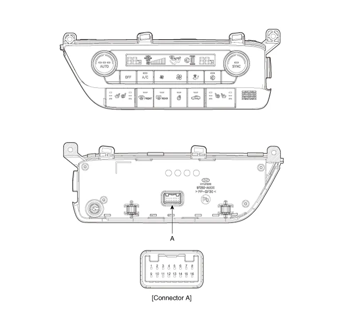
| Components |
| [This illustration shows the LHD type. RHD type is symmetrical.] |
|
Pin No
|
Function
|
Pin No
|
Function
|
| 1 | Battery | 9 | IGN2 |
| 2 | ILL+ (TAIL) | 10 | ISG Battery (+) |
| 3 | - | 11 | IGN1 |
| 4 | LIN BUS | 12 | HTD |
| 5 | - | 13 | - |
| 6 | - | 14 | - |
| 7 | - | 15 | - |
| 8 | RHEO (ILL-) | 16 | Ground |
Repair procedures
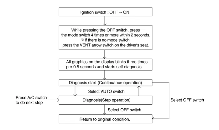
| Self Diagnosis |
| 1. | Self-diagnosis process.
|

| 2. | Fault code display
|


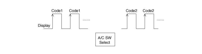
| 3. | If fault codes are displayed during the check, Inspect malfunction causes by referring to fault codes.
|
| 4. | Fail safe
|
| Replacement |
| 1. | Disconnect the negative (-) battery terminal. |
| 2. | Remove the crash pad lower panel. (Refer to Body (Interior and Exterior) - "Crash Pad Lower Panel") |
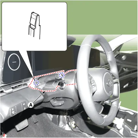
| 3. | Remove the steering column shroud upper panel (A).
|
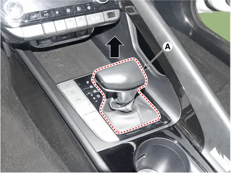
| 4. | Remove the gear knob & boots (A) pull both of it up.
|
| 5. | Using a screwdriver or remover, remove the floor console side garnish (A).
|

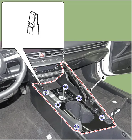
| 6. | Using a screwdriver or remover, remove the console upper cover (A).
|
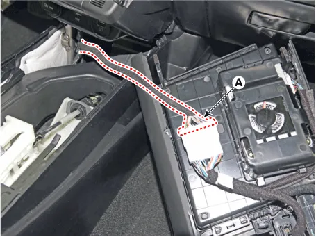
| 7. | Press the lock pin, separate the console upper cover connector (A).
|
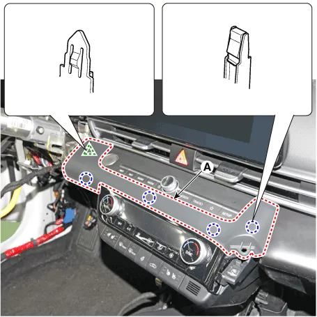
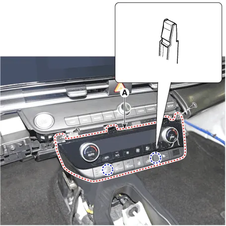
| 8. | Using a screwdriver or remover, remove the crash pad garnish [CTR] (A).
|
| 9. | After loosening the mounting screws, remove the A/C & heater controller unit (A).
|
| 10. | Disconnect the A/C & heater controller connector (A) and hose (B).
|
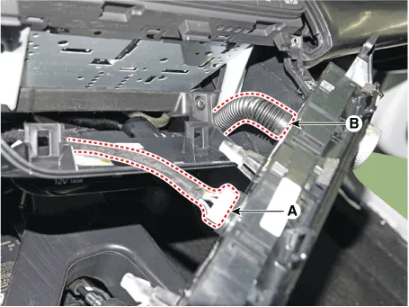
| 11. | To install, reverse the removal procedure.
|
Components and components location Components[This illustration shows the LHD type. RHD type is symmetrical.][Connector A] Pin No Function Pin No Function 1Low (Register specifications)4Middle Low (Register specifications)2Common (Register specifications)5Middle High (Register specifications)3Ground (Register specifications)6High (Register specifications)[Connector B] Pin No Function Pin No Function 1Battery (+)21IGN22ISG B+22IGN13ILL+ (TAIL)23Blower IS (PWM specifications)4Sensor REF (+5V)24-5Mode control actuator (Feedback)25-6Temperature control actuator (Feedback)26-7Intake actuator (Feedback)27Blower Max.
Components and components location Component Location1. Heater control unitComponents[Connector A] Pin No Function Pin No Function 1Mode control actuator (Feedback)21Mode control actuator (Vent)2Intake actuator (Feedback)22Mode control actuator (DEF)3Passenger's temperature control actuator 23Intake actuator (FRE)4Driver's temperature control actuator 24Intake actuator (REC)5DEF actuator feedback25Passenger's temperature control actuator (Cool)6Ionizer diagnosis26Passenger's temperature control actuator (Warm)7-27Driver's temperature control actuator (Cool)8Photo sensor (-) [LH]28Driver's temperature control actuator (Warm)9Photo sensor (-) [RH]29DEF actuator (Open)10-30DEF Driver's temperature control actuator (Coles)11Auto defoging sensor (SDA)31-12Auto defoging sensor (SCL)32-13Auto defoging sensor glass temperature33-14AMB sensor (+)34P_CAN Low15EVAP sensor (+)35P_CAN High16-36Clean signal17-37-18-38-19-39-20-40Ground[Connector B] Pin No Function Pin No Function 1Ground13Ground2Sensor ground14ECV (-) Ground3FET (Gate) (Power mosfet specifications)15ECV (+)4FET (Drain feedback) (Power mosfet specifications)16-5Blower motor (+) (Power mosfet specifications)17-6Blower INH (PWM specifications)18-7Blower IS (PWM specifications)19PTC relay (Gasoline PTC specifications)8Blower PWM IN (PWM specifications)20-9Sensor REF (+5V)21-10-22LIN BUS (PM Sensor)11-23IGN112Battery24IGN2 Repair procedures Replacement1.
Other information:
Hyundai Elantra (CN7) 2021-2025 Service Manual: Heater & A/C Control Unit (Manual)
Components and components location Components[This illustration shows the LHD type. RHD type is symmetrical.][Connector A] Pin No Function Pin No Function 1Low (Register specifications)4Middle Low (Register specifications)2Common (Register
Hyundai Elantra (CN7) 2021-2025 Service Manual: Repair procedures
Variant Coding When you need variant coding:– Replace Front View Camera with a new one※ EOL Variant Coding and calibration required for new replacementFront View Camera Variant CodingFront view camera variant coding makes it possible to operate functions for each vehicle type.
Categories
- Manuals Home
- Hyundai Elantra Owners Manual
- Hyundai Elantra Service Manual
- Engine Mechanical System
- Instrument Cluster
- Towing
- New on site
- Most important about car
