Hyundai Elantra (CN7): Controller / Heater Control Unit
Components and components location
| Component Location |
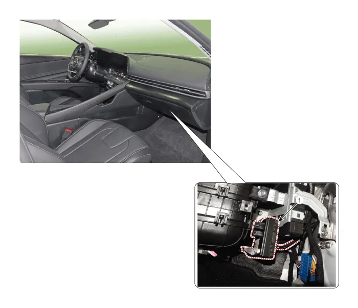
| 1. Heater control unit |
| Components |

|
Pin No
|
Function
|
Pin No
|
Function
|
| 1 | Mode control actuator (Feedback) | 21 | Mode control actuator (Vent) |
| 2 | Intake actuator (Feedback) | 22 | Mode control actuator (DEF) |
| 3 | Passenger's temperature control actuator | 23 | Intake actuator (FRE) |
| 4 | Driver's temperature control actuator | 24 | Intake actuator (REC) |
| 5 | DEF actuator feedback | 25 | Passenger's temperature control actuator (Cool) |
| 6 | Ionizer diagnosis | 26 | Passenger's temperature control actuator (Warm) |
| 7 | - | 27 | Driver's temperature control actuator (Cool) |
| 8 | Photo sensor (-) [LH] | 28 | Driver's temperature control actuator (Warm) |
| 9 | Photo sensor (-) [RH] | 29 | DEF actuator (Open) |
| 10 | - | 30 | DEF Driver's temperature control actuator (Coles) |
| 11 | Auto defoging sensor (SDA) | 31 | - |
| 12 | Auto defoging sensor (SCL) | 32 | - |
| 13 | Auto defoging sensor glass temperature | 33 | - |
| 14 | AMB sensor (+) | 34 | P_CAN Low |
| 15 | EVAP sensor (+) | 35 | P_CAN High |
| 16 | - | 36 | Clean signal |
| 17 | - | 37 | - |
| 18 | - | 38 | - |
| 19 | - | 39 | - |
| 20 | - | 40 | Ground |
|
Pin No
|
Function
|
Pin No
|
Function
|
| 1 | Ground | 13 | Ground |
| 2 | Sensor ground | 14 | ECV (-) Ground |
| 3 | FET (Gate) (Power mosfet specifications) | 15 | ECV (+) |
| 4 | FET (Drain feedback) (Power mosfet specifications) | 16 | - |
| 5 | Blower motor (+) (Power mosfet specifications) | 17 | - |
| 6 | Blower INH (PWM specifications) | 18 | - |
| 7 | Blower IS (PWM specifications) | 19 | PTC relay (Gasoline PTC specifications) |
| 8 | Blower PWM IN (PWM specifications) | 20 | - |
| 9 | Sensor REF (+5V) | 21 | - |
| 10 | - | 22 | LIN BUS (PM Sensor) |
| 11 | - | 23 | IGN1 |
| 12 | Battery | 24 | IGN2 |
Repair procedures
| Replacement |
| 1. | Disconnect the negative (-) battery terminal. |
| 2. | Remove the glove box. (Refer to Body (Interior and Exterior) - "Glove Box") |
| 3. | Separate the heater control unit connector (A) and then loosen the mounitng screw, remove the heater control unit.
|
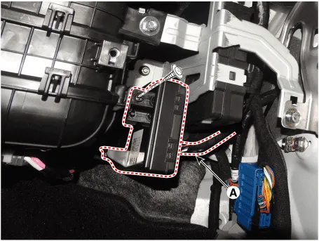
| 4. | To install, reverse the removal procedure.
|

Components and components location Components[This illustration shows the LHD type. RHD type is symmetrical.][Connector A] Pin No Function Pin No Function 1Battery9IGN22ILL+ (TAIL)10ISG Battery (+)3-11IGN14LIN BUS12HTD5-13-6-14-7-15-8RHEO (ILL-)16Ground Repair procedures Self Diagnosis1.
Other information:
Hyundai Elantra (CN7) 2021-2025 Service Manual: Auto Lighting Control System
Description and operation DescriptionIt's a system that uses illumination sensor to automatically turn ON the tail lamp and head lamp based on the change in surrounding environment's illumination condition. It activates when the vehicle enters/exits tunnel, or when the illumination condition in surrounding environment changes due to rain, snow, or
Hyundai Elantra (CN7) 2021-2025 Service Manual: Troubleshooting
TroubleshootingDiagnosis with Diagnostic tool1.In the body electrical system, failure can be quickly diagnosed by using the vehicle diagnostic system (Diagnostic tool).The diagnostic system (Diagnostic tool) provides the following information.1)Fault Code Searching : Checking failure and code number (DTC)2)Data Analysis : Checking the system input/
Categories
- Manuals Home
- Hyundai Elantra Owners Manual
- Hyundai Elantra Service Manual
- Rear Seats
- Recommended Lubricants and Capacities
- Integrated Thermal Management Module (ITM)
- New on site
- Most important about car
