Hyundai Elantra (CN7): Motor Driven Power Steering / MDPS Column and Housing
Repair procedures
| Replacement |
| 1. | Turn the steering wheel so that the front wheels are placed in the straight ahead position.
|

| 2. | Turn the ignition switch OFF and disconnect the battery negative (-) cable.
|

| 3. | Remove driver airbag (DAB) module. (Refer to Restraint - "Driver Airbag (DAB) Module and Clock Spring") |
| 4. | Remove the steering wheel. (Refer to Steering System - "Steering Wheel") |
| 5. | Remove the clock spring. (Refer to Restraint - "Driver Airbag (DAB) Module and Clock Spring") |
| 6. | Remove the steering column shroud panel. (Refer to Body - "Steering Column Shroud Panel") |
| 7. | Remove the crash pad lower panel. (Refer to Body - "Crash Pad") |
| 8. | Remove the brake booster. (Only RHD) (Refer to Brake System - "Brake Booster") |
| 9. | Remove the brake pedal. (Only RHD) (Refer to Brake System - "Brake Pedal") |
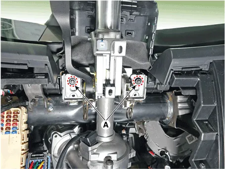
| 10. | Disconnect the MDPS connector (A).
|
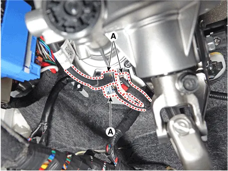
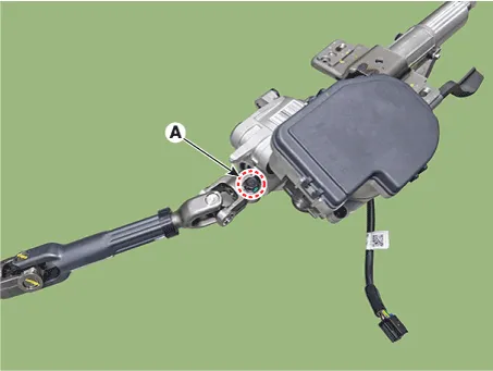
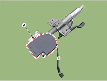
| 11. | Remove the wiring clip (A) from the steering column.
|
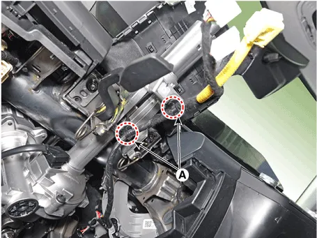
| 12. | Separate the universal joint from the steering gear box after loosening the universal joint mounting bolt (A).
|

| 13. | Remove the steering column assembly after loosening the mounting nuts (A) and bolt (B).
|

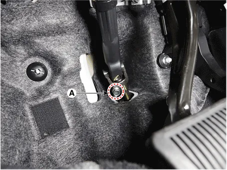
| 14. | Separate the steering column assembly and universal joint assembly after loosening the mounting bolt (A).
|
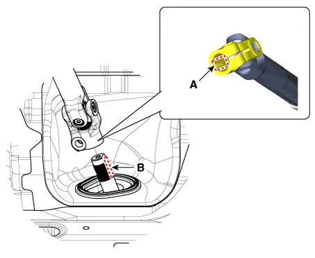
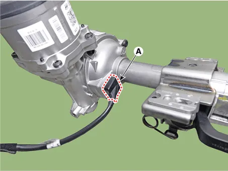
| 15. | Disconnet the grommet (A).
|
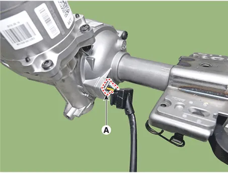
| 16. | Disconnect the MDPS wiring connector (A).
|
| 17. | Remove the MDPS power pack (A) after loosening the mounting bolts.
|
| 18. | To install, reverse the removal procedures. |
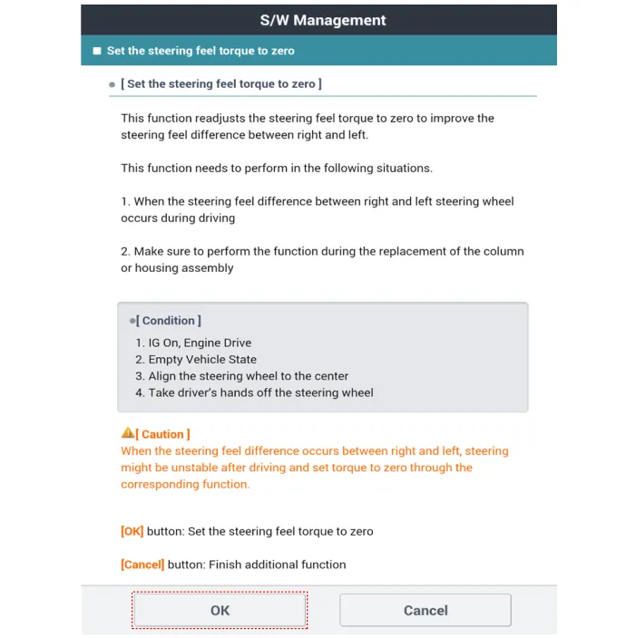
| 19. | Set the Steering angle zero point by using the diagnostic tool.
|
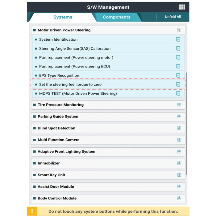
| 20. | Conduct the "EPS Type Recognition" by diagnostic tool. (Refer to MDPS PowerPack Assembly - "Diagnosis with diagnostic tool") |
| 21. | Conduct the "ASP Calibration" by diagnostic tool. (Refer to MDPS PowerPack Assembly - "Diagnosis with Diagnostic tool") |
| 22. | Conduct the MDPS Performance Inspection using the diagnostic tool. (Refer to Motor Driven Power Steering - "MDPS Performance Inspection") |
| 23. | Check the DTC. |
| 24. | Turn off the IGN switch and wait for 20 seconds or more. Then check the operation after starting the engine. |
| 1. | Remove the crash pad lower panel. (Refer to Body (Interior and Exterior) - "Crash Pad Lower Pannel") |
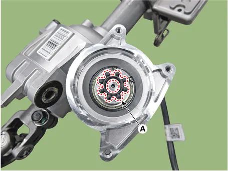
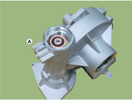
| 2. | Remove the small bearing cover (A).
|

| 3. | Remove the small bearing (A) by rotating in the direction of the arrow after installing the SST (09563-IB000).
|

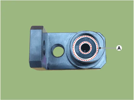
| 4. | Install the new small bearing (A) to the SST (0956-IB200).
|
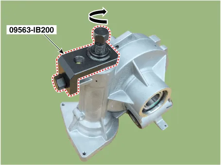
| 5. | Press the small bearing by rotating in the direction of the arrow after installing the SST (09563-IB000).
|
Repair procedures Replacement1.Turn the steering wheel so that the front wheels are placed in the straight ahead position. • If the steering wheel and the front tires are not set straight ahead together, it may affect the number of circulation of steering wheel and damage the cable inside the clock spring.
Repair procedures Removal1.Loosen the wheel nuts slightly.Raise the vehicle, and make sure it is securely supported.2.Remove the front wheel and tire (A) from the front hub.
Other information:
Hyundai Elantra (CN7) 2021-2026 Service Manual: Antenna Coil
Repair procedures Removal1.Disconnect the negative (-) battery terminal.2.Remove the crash pad lower panel.(Refer to Body - "Crash Pad Lower Panel")3.Remove the steering column shroud panel.(Refer to Body - "Steering Column Shroud Panel")4.Disconnect the immobilizer connector (A) and press the locking pin (B) using an awl.
Hyundai Elantra (CN7) 2021-2026 Service Manual: Front Radar Unit
Components and components location Components Location1. Front rader unit Specifications Specification Item Specification Power supply (V)12Operation voltage (V)9 - 16 Schematic diagrams Circuit DiagramTerminal function Pin No Te
Categories
- Manuals Home
- Hyundai Elantra Owners Manual
- Hyundai Elantra Service Manual
- Suspension System
- Front Radar Unit
- Recommended Cold Tire Inflation Pressures
- New on site
- Most important about car
