Hyundai Elantra: IMS(Integrated Memory System) / Memory power seat unit
Hyundai Elantra (CN7) 2021-2025 Service Manual / Body Electrical System / IMS(Integrated Memory System) / Memory power seat unit
Components and components location
| Components |
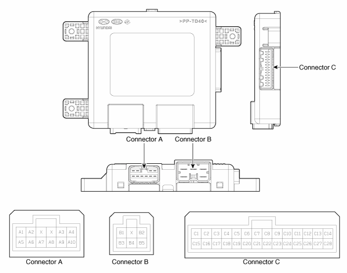
Connector Pin Information
|
Pin no
|
Connector A
|
Connector B
|
Connector C
|
| 1 | - | B (+) | Slide switch signal (Forward) |
| 2 | Reclining motor (Forward) | GND(Power) | Reclining switch signal (Forward) |
| 3 | Height motor (Up) | B (+) | Front tilt switch signal (Up) |
| 4 | Slide motor (Forward) | - | Height switch (Up) |
| 5 | - | GND | Reclining limit switch signal (Forward) |
| 6 | Reclining motor (Backward) | B_CAN (High) | |
| 7 | Tilt motor (Up) | B_CAN (Low) | |
| 8 | Tilt motor (Down) | - | |
| 9 | Height motor (Down) | Driver lumber motor (Mid) | |
| 10 | Slide motor (Backward) | Seat slide sensor | |
| 11 | Seat tilt sensor | ||
| 12 | - | ||
| 13 | Seat position sensor power | ||
| 14 | IGN 1 | ||
| 15 | Seat slide switch (Backward) | ||
| 16 | Seat recline switch (Backward) | ||
| 17 | Tilt switch (Down) | ||
| 18 | Height switch (Down) | ||
| 19 | Reclining limit switch signal (Backward) | ||
| 20 | GND | ||
| 21 | - | ||
| 22 | IMS Switch | ||
| 23 | Driver lumber motor (Def) | ||
| 24 | Reclining sensor | ||
| 25 | Height sensor | ||
| 26 | - | ||
| 27 | - | ||
| 28 | B(+) |
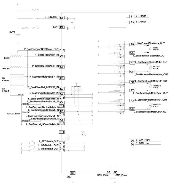
Schematic diagrams
| Circuit Diagram |
Repair procedures
| Removal |
| 1. | Disconnect the negative (-) battery terminal. |
| 2. | Remove the driver seat assembly. (Refer to Body - "Front Seat Assembly") |
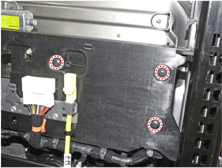
| 3. | Loosening the IMS unit mounting screws.
|
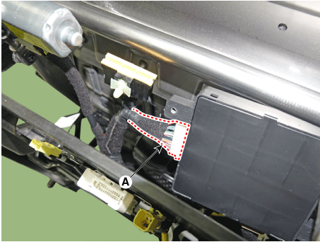
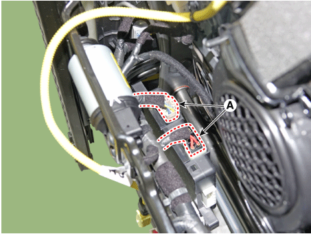
| 4. | Disconnect IMS module connectors (A) and then remove the IMS unit.
|
| Installation |
| 1. | Install the memory power seat unit. |
| 2. | Install the driver seat assembly. |
| 3. | Connect the negative (-) battery terminal. |

 Memory power seat switch
Components and components location
Components
Repair procedures
Removal1.Disconnect the negative (-) battery terminal.2.Remove the driver door trim...
Other information:
Hyundai Elantra (CN7) 2021-2025 Owner's Manual: Tire Specification and Pressure Label, Engine Number
Tire Specification and Pressure Label The tires supplied on your new vehicle are chosen to provide the best performance for normal driving. The tire label located on the driver’s side center pillar gives the tire pressures recommended for your car...
Hyundai Elantra (CN7) 2021-2025 Service Manual: Repair procedures
Removal • Put on gloves to prevent hand injuries. • Use seat covers to avoid damaging any surfaces. 1.Remove the roof side molding.(Refer to Body Side Moldings - "Roof Side Molding")2...
Categories
- Manuals Home
- 7th Gen Hyundai Elantra Owners Manual
- 7nd Gen Hyundai Elantra Service Manual
- Dimensions, Engine specification, Bulb Wattage
- Vehicle Information
- System operation
- Function settings
- Fuel gauge
Rear center seat belt
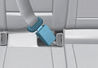
When using the rear center seat belt, the buckle with the “CENTER” mark must be used.
WARNING
Make sure that the seatback is locked in place when using the rear center seat belt.
If not, the seatback may move when there is a sudden stop or collision, which could result in serious injury.

Copyright © 2025 www.helantra7.com