Hyundai Elantra: Rear Glass Defogger / Rear Glass Defogger Switch
Hyundai Elantra (CN7) 2021-2025 Service Manual / Body Electrical System / Rear Glass Defogger / Rear Glass Defogger Switch
Repair procedures
| Diagnosis with Diagnostic tool |
Diagnosis with Diagnostic tool
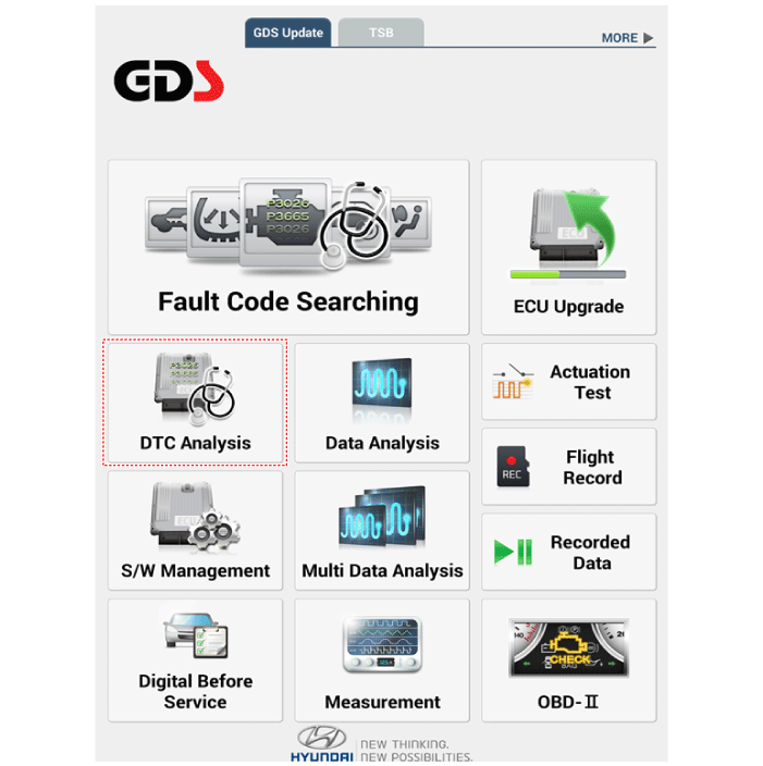
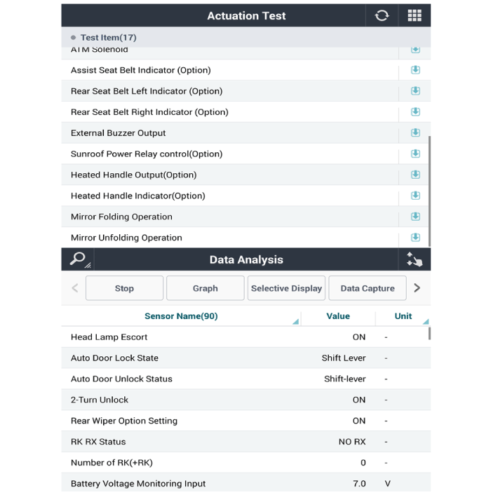
| 1. | In the body electrical system, failure can be quickly diagnosed by using the vehicle diagnostic system (Diagnostic tool). The diagnostic system (Diagnostic tool) provides the following information.
|
| 2. | If diagnose the vehicle by Diagnostic tool, select "DTC Analysis" and "Vehicle".
|
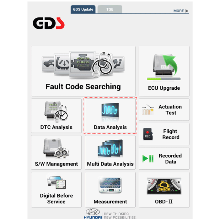
| 3. | Select the 'Data Analysis' and 'Car model'.
|
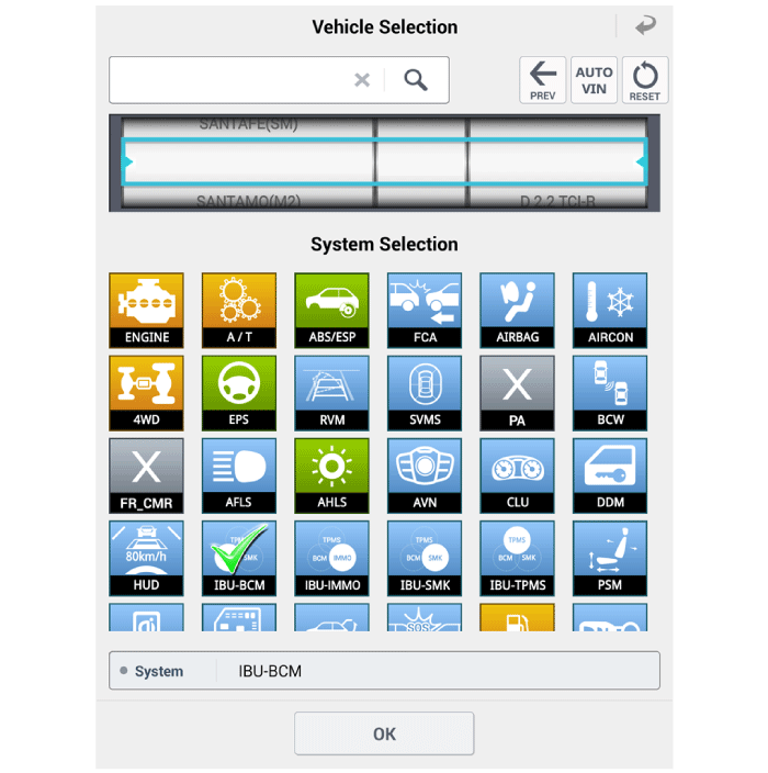
| 4. | Select the 'IBU_BCM' to search the current state of the input/output data.
|
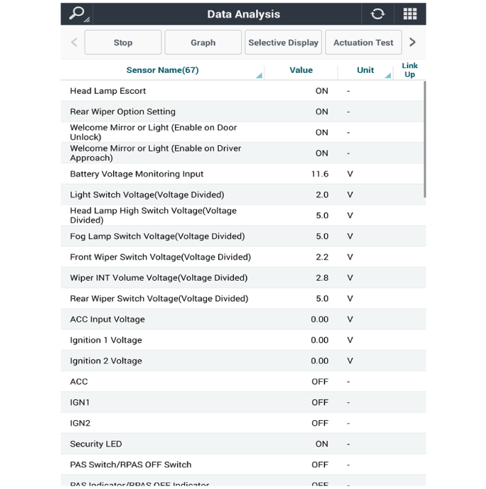
| 5. | To forcibly actuate the input value of the module to be checked, select option 'Actuation Test'.
|
| Removal |
| 1. | Disconnect the negative (-) battery terminal. |
| 2. | Remove the heater and A/C controll unit. (Refer to Heating, Ventilation, Air conditioning - "Heater & A/C Control Unit (Dual)") |
| Installation |
| 1. | Install the heater and A/C control unit. |
| 2. | Connect the negative (-) battery terminal. |
 Rear Glass Defogger Printed Heater
Repair procedures
Inspection
•
Wrap tin foil around the end of the voltmeter test lead to prevent damaging the heater line...

Other information:
Hyundai Elantra (CN7) 2021-2025 Service Manual: Front Door Side Weatherstrip
Repair procedures Replacement[Front door side weatherstrip]1.Loosen the front door checker (B) mounting bolt. Tightening torque : 18.6 - 28.4 N.m (1.7 - 2.2 kgf.m,13.7 - 21.0 lb-ft)2.Detach the clips, then remove the front door side weatherstrip (A).3.To install, reverse the removal procedure. • Replace any damaged clips (or p..
Hyundai Elantra (CN7) 2021-2025 Service Manual: Manifold Absolute Pressure Sensor (MAPS)
Description and operation DescriptionManifold Absolute Pressure Sensor (MAPS) is a speed-density type sensor and is installed on the surge tank. It senses absolute pressure of the surge tank and transfers the analog signal proportional to the pressure to the ECM. By using this signal, the ECM calculates the intake air quantity and engine speed.The MAPS consists of a piezo-electric element and a..
Categories
- Manuals Home
- 7th Gen Hyundai Elantra Owners Manual
- 7nd Gen Hyundai Elantra Service Manual
- Engine Oil
- Function settings
- System disabled
- Drive Mode
- Vehicle Information
Tachometer
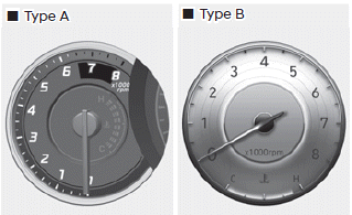
The tachometer indicates the approximate number of engine revolutions per minute (RPM).
Use the tachometer to select the correct shift points and to prevent lugging and/ or over-revving the engine.
NOTICE
Do not operate the engine within the tachometer's RED ZONE. This may cause severe engine damage.

Copyright © 2025 www.helantra7.com