Hyundai Elantra (CN7): Keyless Entry And Burglar Alarm / Repair procedures
Hyundai Elantra (CN7) 2021-2026 Service Manual / Body Electrical System / Keyless Entry And Burglar Alarm / Repair procedures
| Inspection |
|

Front Door Lock Module Inspection
| 1. | Remove the front door trim. (Refer to Body - "Front Door Trim") |
| 2. | Remove the front door module. (Refer to Body - "Front Door Module") |
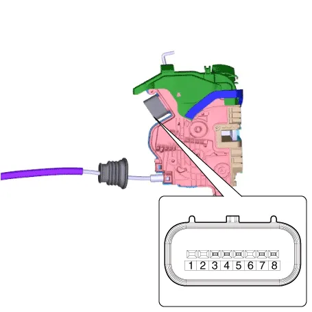
| 3. | Disconnect the connector from the actuator.
| |||||||||||||||||||||||||||||
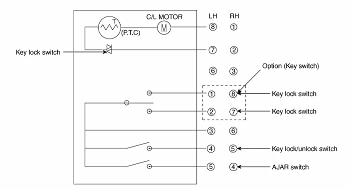
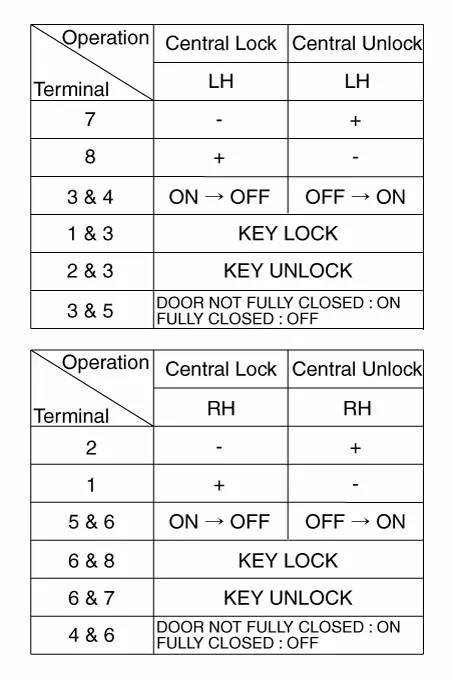
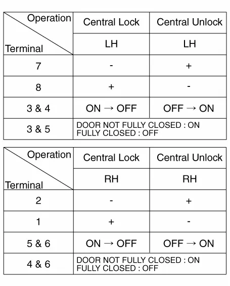
| 4. | Check actuator operation by connecting power and ground according to the table. To prevent damage to the actuator, apply battery voltage only momentarily.
|
Rear Door Lock Module Inspection
| 1. | Remove the rear door trim. (Refer to Body - "Rear Door Trim") |
| 2. | Remove the rear door module. (Refer to Body - "Rear Door Module") |
| 3. | Disconnect the connectors from the actuator.
| |||||||||||||||||||||||||||||
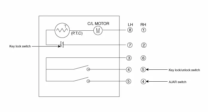
| 4. | Check actuator operation by connecting power and ground according to the table. To prevent damage to the actuator, apply battery voltage only momentarily.
|
Tailgate Lock Module Inspection
| 1. | Remove the trunk lid trim. (Refer to Body - "Trunk Lid Trim") |
| 2. | Disconnect the connector from the actuator
|
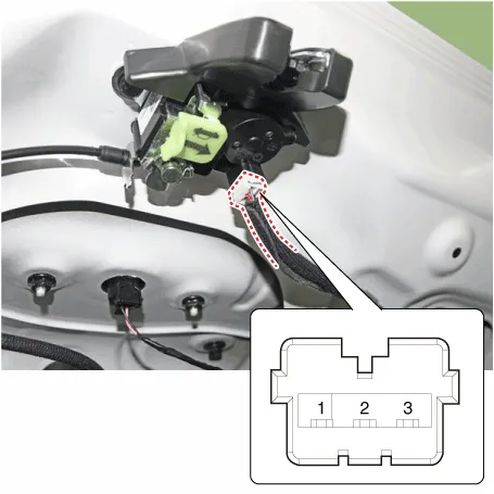
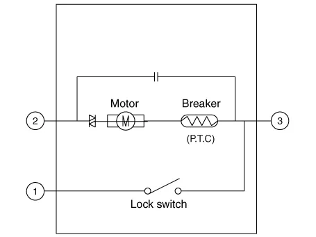
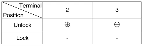
| 3. | Check actuator operation by connecting power and ground according to the table. To prevent damage to the actuator, apply battery voltage only momentarily.
|

| 4. | Checking the trunk of the vehicle power option power refers to the trunk module. |
Hood Switch
| 1. | Disconnect the connector (A).
|
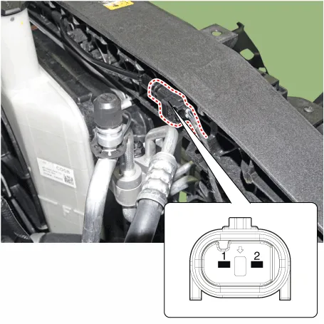
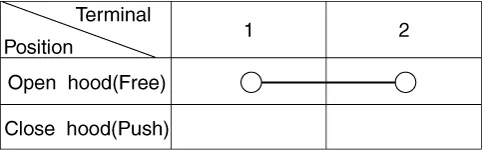
| 2. | Check for continuity between the terminals and ground according to the table (Refer to Body - "Hood Latch")
|
Specification Item Specification Power source3VOperating temperature-10°C ~ +60°CRF ModulationFSKLF ModulationASKRF frequency433.
Other information:
Hyundai Elantra (CN7) 2021-2026 Service Manual: A/C Pressure Transducer
Description and operation DescriptionThe A/C Pressure Transducer (APT) converts the pressure value of high pressure line into voltage value after measuring it. By converted voltage value, engine ECU controls the cooling fan by operating it high speed or low speed.
Hyundai Elantra (CN7) 2021-2026 Service Manual: Parking Distance Warning (PDW)
Description and operation Description• PDW consists of 8 sensors (front : 4 units, rear : 4 units) that are used to detect obstacles and transmit the result in three separate warning levels, the first, second and third to IBU via LIN communication.
Categories
- Manuals Home
- Hyundai Elantra Owners Manual
- Hyundai Elantra Service Manual
- Maintenance
- Driver assistance system
- Front Radar Unit
- New on site
- Most important about car

Copyright © 2026 www.helantra7.com - 0.0202