Hyundai Elantra (CN7): Dual Clutch Transmission Control System / Shift Cable
Components and components location
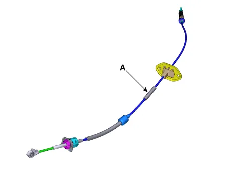
| Components |

| 1. Shift lever knob & boots assembly 2. Shift lever assembly 3. Shift cable | 4. Manual control lever 5. Shift cable retainer |
Repair procedures
| Removal |
| 1. | Remove the air cleaner assembly and air duct. (Refer to Engine Mechnical System - "Air cleaner") |
| 2. | Remove the battery and tray. (Refer to Engine Electrical System - "Battery") |
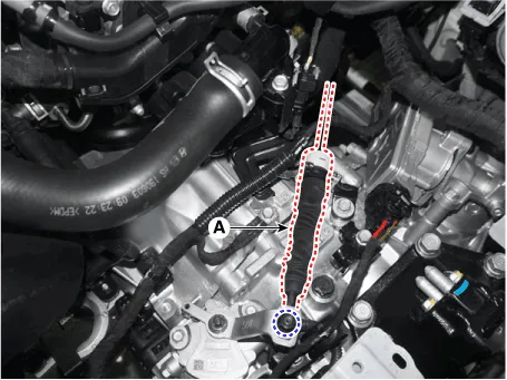
| 3. | Remove the shift cable (A) from the cable bracket, after loosening the mounting nut.
|
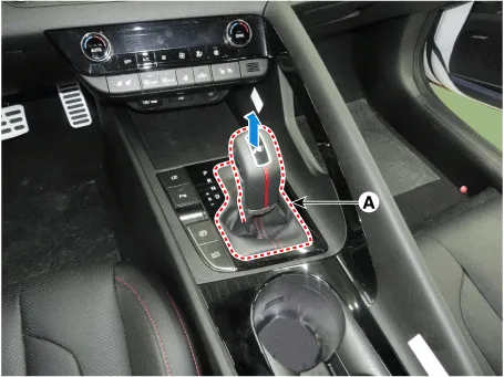
| 4. | Remove the shift lever knob & boots (A).
|
| 5. | Remove the floor console assembly. (Refer to Body - "Floor Console") |
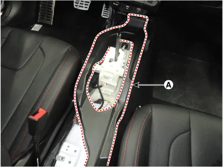
| 6. | Remove the air duct (A) after loosening the bolts.
|
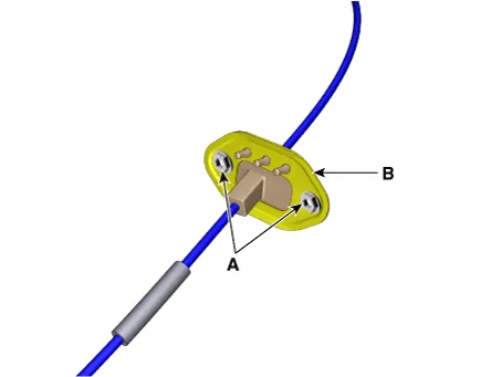
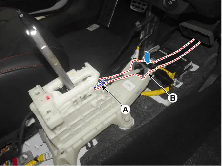
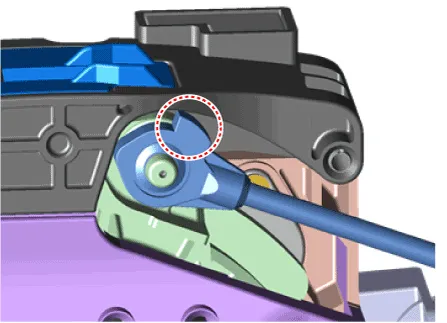
| 7. | Separate the shift cable sorket (B) after removing the snap pin (A).
|

| 8. | Remove the retainer (B) by loosening the nuts (A).
|
| 9. | Remove the shift cable (A) from the vehicle.
|
| Installation |
| 1. | Install the retainer (B) and then tighten the nut (A).
|
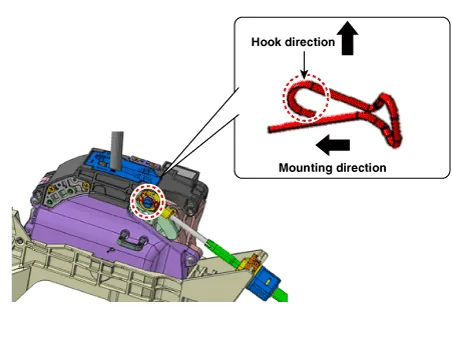
| 2. | Install the shift cable sorket (B) and then fix the snap pin (A).
|

| 3. | Install the air duct (A).
|
| 4. | Install the floor console assembly. (Refer to Body - "Floor Console") |
| 5. | Install the shift lever knob & boots (A).
|

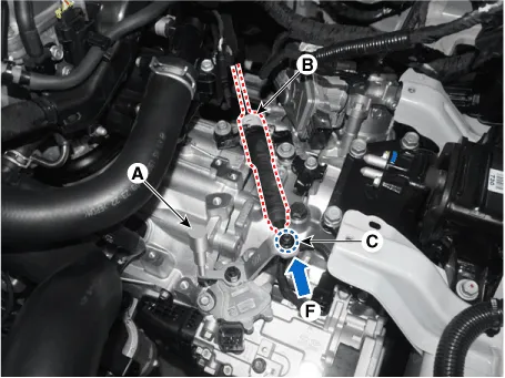
| 6. | Align the hole in the manual control lever with the "N" position hole of the inhibitor switch and then insert the inhibitor switch guide pin (SST No. : 09480 - A3800) (A) in the matched hole. |
| 7. | Push shift cable (B) lightly to "F" direction shown to eliminate free play of shift cable. |
| 8. | Tighten the nut (C) with the specified torque.
|
| 9. | Remove the inhibitor switch guide pin (SST No.:09480-A3800) from the hole. |
| 10. | Install the battery and tray. (Refer to Engine Electrical System - "Battery") |
| 11. | Install the air cleaner assembly and air duct. (Refer to Engine Mechnical System - "Air cleaner")
|
Components and components location Components1. Shift lever knob & boots assembly2. Shift lever assembly3. Shift cable4. Manual control lever5. Shift cable retainer Repair procedures Removal1.
Other information:
Hyundai Elantra (CN7) 2021-2026 Service Manual: Description and operation
DescriptionSystem OverviewThe System offers the following features:– Human / machine interface through a 1-stage button, for terminal switching and engine start.– Control of external relays for ACC / IGN1 / IGN2 terminal switching and STARTER, without use of mechanical ignition switch.
Hyundai Elantra (CN7) 2021-2026 Service Manual: Description and operation
Description and OperationBlcok Diagram • This system monitors the driving situations through the radar and the camera. Thus, for a situation out of the sensing range, the system may not normally operate. The System may be limited when : • The radar sensor or camer
Categories
- Manuals Home
- Hyundai Elantra Owners Manual
- Hyundai Elantra Service Manual
- Rear Seats
- Maintenance
- Body (Interior and Exterior)
- New on site
- Most important about car
