Hyundai Elantra (CN7): Front Radar System / Smart Cruise Control (SCC) Switch
Schematic diagrams
| Circuit Diagram |

Repair procedures
| Inspection |
| 1. | Check for resistance between terminals in each switch position (LH).
[LH : Audio + Hands free]
|

| 2. | Check for resistance between terminals in each switch position (RH).
[Cruise]
[Trip]
|
| Removal |
| 1. | Disconnect the negative (-) battery terminal. |
| 2. | Remove the steering wheel assembly. (Refer to Steering System - "Steering Wheel") |
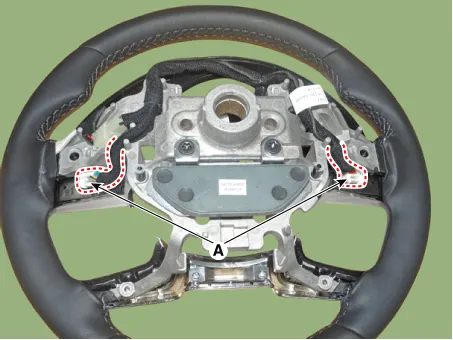
| 3. | Remove the steering back cover (A).
|

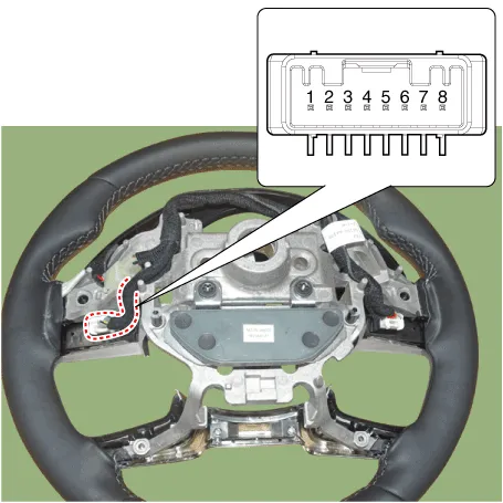
| 4. | Remove the steering remote control connector (A).
|
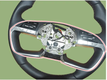
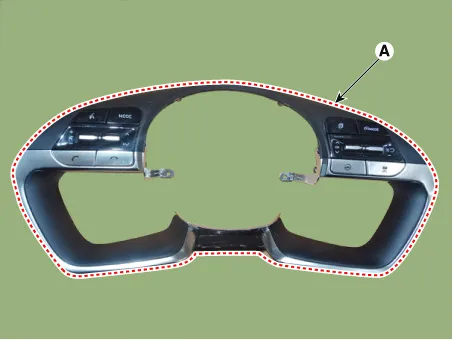
| 5. | Remove the steering remote control(Switch (A)) after loosening the screws.
|
| Installation |
| 1. | Install the steering wheel remote control after connecting the connector. |
| 2. | Install the steering wheel. |
| 3. | Connect the negative (-) battery terminal. |
Components and components location Components Location1. Front rader unit Specifications Specification Item Specification Power supply (V)12Operation voltage (V)9 - 16 Schematic diagrams Circuit DiagramTerminal function Pin No Terminal function 1GROUND2L-CAN HIGH3L-CAN LOW4C-CAN HIGH5C-CAN LOW6IGN Repair procedures InspectionInspection procedure for vehicle with Forward Collision-Avoidance Assist and Smart Cruise Control system failure 1.
Other information:
Hyundai Elantra (CN7) 2021-2026 Service Manual: Troubleshooting
TroubleshootingWireless Power Charger System Troubleshooting Trouble status Inspection item Inspection Not chargedCheck the mobile phone status R-1Amber LED blinks OvercurrentR-2OverheatingR-2Foreign matterR-2R-1.
Hyundai Elantra (CN7) 2021-2026 Service Manual: Troubleshooting
Trouble Symptom ChartsTrouble Symptom 1Trouble Symptom 2 Trouble symptom Probable cause Remedy The set vehicle speed varies greatly upward or downward"Surging" (repeated alternating acceleration and deceleration) occurs after settingMalfunction of the vehicle speed se
Categories
- Manuals Home
- Hyundai Elantra Owners Manual
- Hyundai Elantra Service Manual
- Body (Interior and Exterior)
- Instrument Panel Overview
- Brake System
- New on site
- Most important about car
