Hyundai Elantra (CN7): Smart Key System / Smart Key Unit
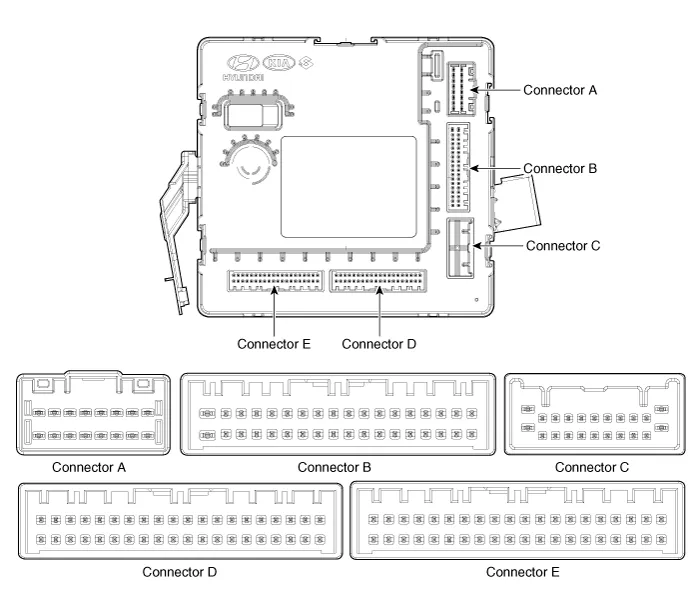
Components and components location
| Components (1) |
|
Pin no
|
Connector A
|
Connector B
|
Connector C
|
Connector D
|
Connector E
|
| 1 | ESCL (+)_output | - | - | - | - |
| 2 | Front heated nozzle_output | - | - | - | - |
| 3 | - | Puddle pocket lamp_output | - | Mirror folding_output | - |
| 4 | Front washer switch _Input | - | - | - | |
| 5 | - | LIN(PDW) | - | - | ESCL enable_output |
| 6 | Ground_Power | R-PDW power_input | - | - | RPM_input |
| 7 | Ground_ECU | R-PDW power_output | - | - | Start relay_output |
| 8 | ESCL (-)_output | F-PDW power_output | - | - | ACC relay_output |
| 9 | Battery (+) ECU | ATM solenoid_output | - | Auto light sensor ground_output | Start feedback_input |
| 10 | Battery (+) Power | Head lamp high beam switch_input | - | Rear view camera switch_input | SSB switch2_input |
| 11 | IGN_Input | Front washer switch _Input | - | R-PDW switch_input | Trunk antenna (-)_output |
| 12 | Kiline_IMMO | Front wiper INT volume switch_input | - | P-Position_input | Interior2 antenna power(-)_output |
| 13 | - | Wiper parking switch_input | - | Passenger outside handle switch_input | - |
| 14 | - | External buzzer_output | - | Multifunction Switch ground _Input | Passenger outside handle antenna (-)_output |
| 15 | - | R-PDW switch IND_output | - | ACC_input | - |
| 16 | - | - | - | IGN2_input | - |
| 17 | - | - | Front wiper low back up switch_input | - | |
| 18 | - | - | Brake switch_input | Driver outside handle antenna (-)_output | |
| 19 | - | - | - | Immobilizer antenna ground_output | |
| 20 | - | - | - | - | |
| 21 | - | - | - | - | |
| 22 | LIN 3(Rain sensor) | - | PDW option_input | - | |
| 23 | Wiper power relay_output | Mirror unfolding_output | - | ||
| 24 | - | - | - | ||
| 25 | Wiper low relay_output | - | - | ||
| 26 | Wiper high relay_output | - | Wheel speed sensor_input | ||
| 27 | - | - | IGN2 relay_output | ||
| 28 | Fog lamp switch_input | - | IGN1 relay_output | ||
| 29 | Light switch_input | Auto light sensor power_output | SSB symbol illumination(+)_output | ||
| 30 | - | Auto light sensor signal_input | SSB switch1_input | ||
| 31 | - | Sunroof status_input | Trunk antenna (+)_output | ||
| 32 | - | ESCL unlock switch_input | Interior2 antenna power(+)_output | ||
| 33 | ESCL_COM | Clutch lock switch_input (MT) | - | ||
| 34 | EMS ECU wake up_output/Dood unlock signal_output | Driver outside handle switch_input | Passenger outside handle antenna (+)_output | ||
| 35 | - | B-CAN High | - | ||
| 36 | - | B-CAN Low | - | ||
| 37 | P-CAN High | - | |||
| 38 | P-CAN Low | Driver outside handle antenna (+)_output | |||
| 39 | - | Immobilizer antenna power_output | |||
| 40 | - | - |
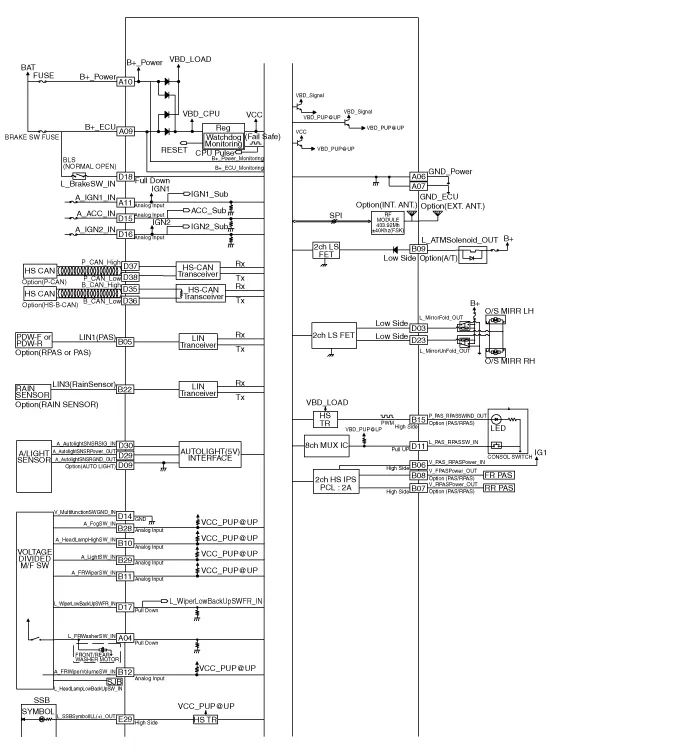
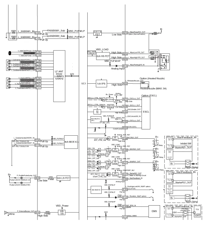
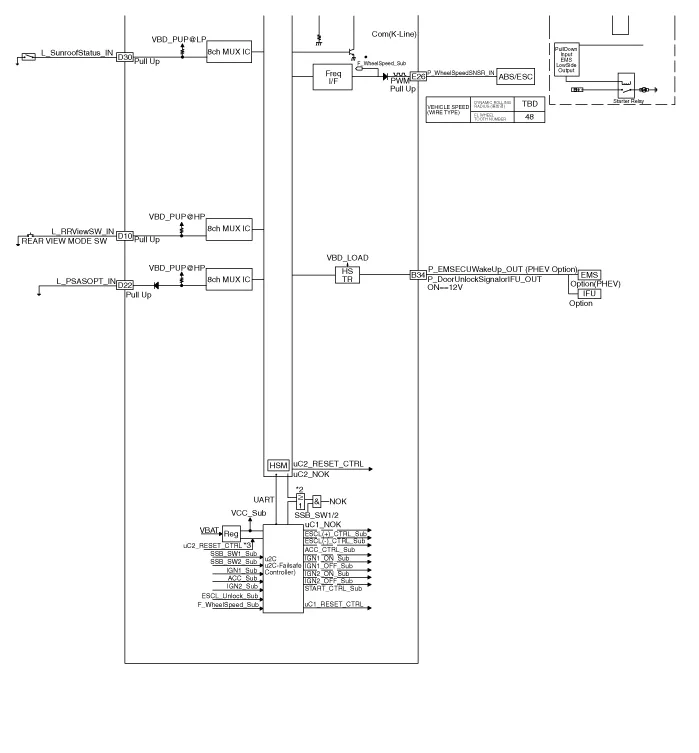
Schematic diagrams
| Circuit Diagram |
Repair procedures
| Removal |
| 1. | Disconnect the negative (-) battery terminal. |
| 2. | Remove the glove box housing cover.. (Refer to Body - "Glove Box Housing Cover.") |
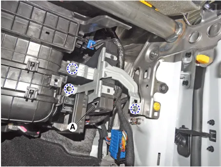
| 3. | Remove the smart key unit(IBU) (A) after loosening bolt and nuts.
|
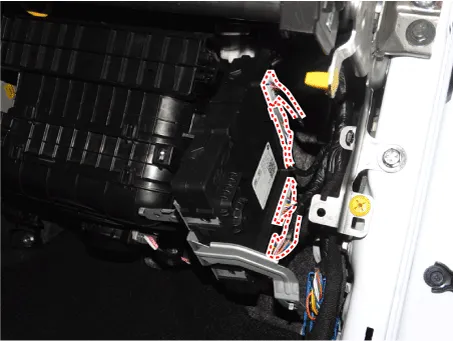
| 4. | Disconnect smart key unit (IBU) connectors.
|
| Inspection |
| Installation |
| 1. | Install the smart key unit. |
| 2. | Install the smart key unit mounting bolts and connect the connector. |
| 3. | Install the Glove box housing cover.. |
| 4. | Install the negative (-) battery terminal and check the smart key system. |
Repair procedures Smart KeySmart Key Code Saving1.Connect the DLC cable of Diagnostic tool to the data link connector (16 pins) in driver side crash pad lower panel, turn the power on Diagnostic tool.
Repair procedures InspectionSelf Diagnosis With Scan ToolIt will be able to diagnose defects of SMART KEY system with Diagnostic tool quickly. Diagnostic tool can operates actuator forcefully, input/output value monitoring and self diagnosis.
Other information:
Hyundai Elantra (CN7) 2021-2026 Service Manual: Wireless Power Charging Unit
Components and positions Components Circuit diagram Circuit Diagram Repair procedures Removal • Handling wireless charging system parts by wet hands may cause electric shock. 1.Disconnect the negative (-) battery terminal.
Hyundai Elantra (CN7) 2021-2026 Service Manual: Description and operation
DescriptionThe cruise control system is engaged by the cruise "ON/OFF" main switch located on right of steering wheel column. The system has the capability to cruise, coast, accelerate and resume speed.It also has a safety interrupt, engaged upon depressing brake or shifting select lever.
Categories
- Manuals Home
- Hyundai Elantra Owners Manual
- Hyundai Elantra Service Manual
- Driver assistance system
- Drive Mode
- General Tightening Torque Table. General information
- New on site
- Most important about car
