Hyundai Elantra (CN7): Brake System / Stop Lamp Switch
Components and components location
| Components |
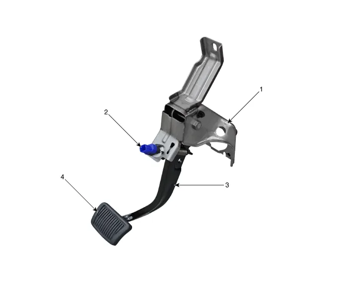
| 1. Brake member assembly 2. Stop lamp switch | 3. Brake pedal arm assembly 4. Brake pedal pad |
Troubleshooting
| Troubleshooting |
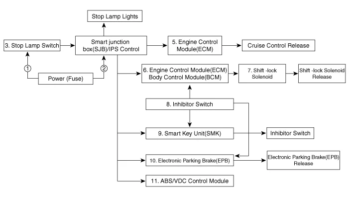
| 1. | Part diagnosis
|
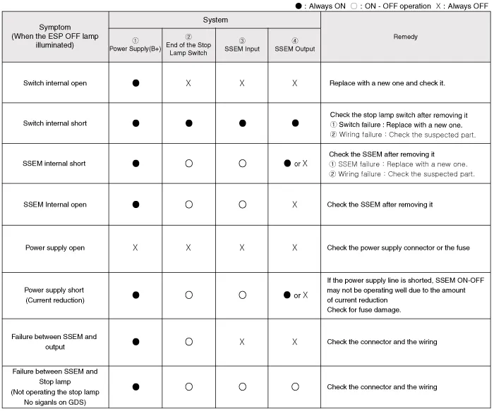
| 2. | Symptom diagnosis
|
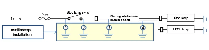
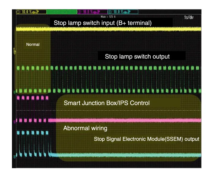
| 3. | Stop lamp switch system diagnosis
SSEM : Stop Signal Electronic Module |
| 4. | Refer to DTC guide when the related DTC codes are displayed. |
Schematic diagrams
| Schematic Diagram |
| System Circuit Diagram |
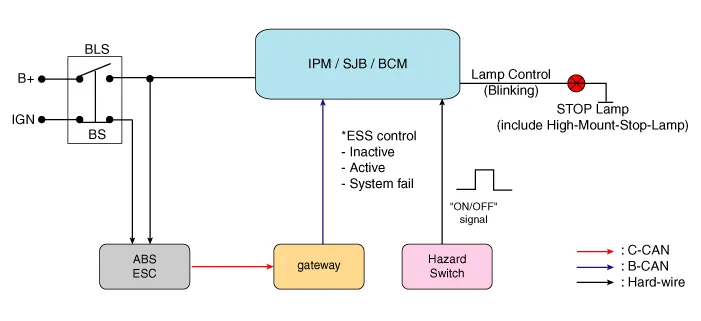
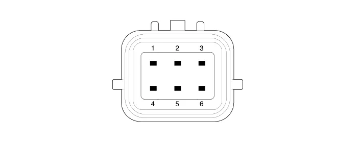
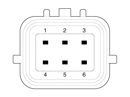
| Terminal Function |
|
Teminal
|
Description
|
| 1 | IGN1 |
| 2 | Engine Control Module (ECM) |
| 3 | - |
| 4 | B+ |
| 5 | Stop Lamp |
| 6 | Gruound |
Repair procedures
| Adjustment |
| 1. | Turn ignition switch OFF and disconnect the negative (-) battery cable. |
| 2. | Remove the lower crash pad. (Refer to Body - "Crash Pad") |
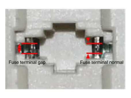
| 3. | Confirm the gap between stop lamp switch and bracket.
|
| 4. | If the gap between stop lamp switch and bracket is not 1.0-2.0 mm (0.04-0.08 in), check the mounting clip and other part of around stop lamp. |
| 5. | If there is normal, remove the stop lamp switch and then install again. |
| Inspection |
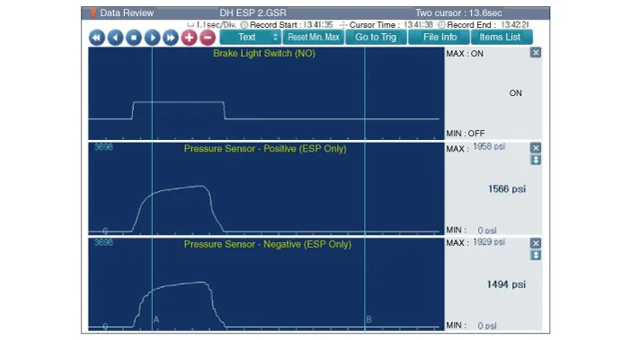
| 1. | Analyze GDS data and confirm if there is anything wrong with the stop lamp switch.
|
| Removal |
| 1. | Turn ignition switch OFF and disconnect the negative (-) battery cable. |
| 2. | Remove the lower crash pad. (Refer to Body - "Crash Pad") |
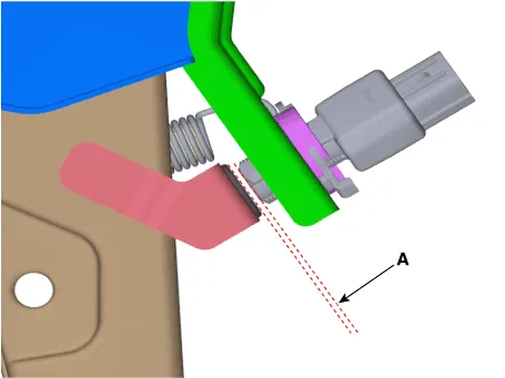
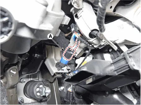
| 3. | Disconnect the stop lamp switch connector (A).
|
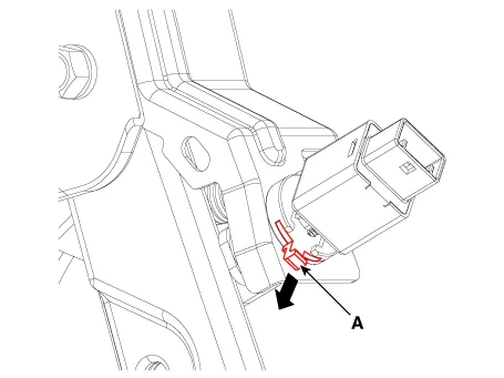
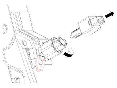
| 4. | Pull the locking plate (A) as indicated by the arrow.
|
| 5. | Turn stop lamp switch 45° counterclockwise and remove it.
|
| 6. | Inspect a removed stop lamp switch along the below procedures.
|
| Installation |
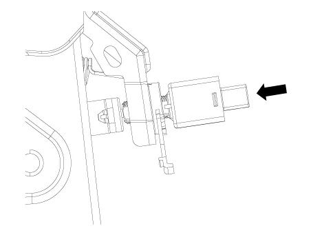
| 1. | Insert fully the stop lamp switch as hiding contact part.
|
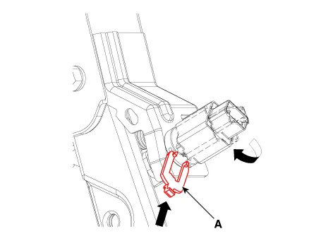
| 2. | After inserting, turn the stop switch 45° clockwise, and then assemble locking plate (A) by pushing.
|
| 3. | Confirm the gap between stop lamp switch.
|

| 4. | Connect the stop lamp switch connector (A).
|
| 5. | Install the lower crash pad. (Refer to Body - "Crash Pad") |
Repair procedures Replacement[Front]1.Loosen the wheel nuts slightly.Raise the vehicle, and make sure it is securely supported.2.Remove the front wheel and tire (A) from the front hub.
Other information:
Hyundai Elantra (CN7) 2021-2026 Service Manual: Mood Lamp
Repair procedures RemovalMood lamp unit1.Disconnect the negative (-) battery terminal.2.Remove the main crash pad assembly.(Refer to Body - "Main Crash Pad Assembly")3.Loosen the mounting screws and remove the main crash pad air duct (A).4.Loosen the mounting screws and remove the mood lamp unit (A).
Hyundai Elantra (CN7) 2021-2026 Service Manual: Compressor oil
Repair procedures Oil Specification1.The HFC-134a system requires synthetic (PAG) compressor oil whereas the R-12 system requires mineral compressor oil. The two oils must never be mixed.2.Compressor (PAG) oil varies according to compressor model. Be sure to use oil specified for the model of compressor.
Categories
- Manuals Home
- Hyundai Elantra Owners Manual
- Hyundai Elantra Service Manual
- Instrument Panel Overview
- Front Radar Unit
- Integrated Thermal Management Module (ITM)
- New on site
- Most important about car
