Hyundai Elantra (CN7): Tire Pressure Monitoring System / Troubleshooting
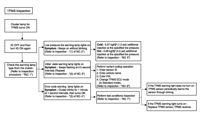
| TPMS Inspection method |
Components1. Integrated Body Control Unit (IBU)2. TPMS sensor (FL)3. TPMS sensor (RL)4. TPMS sensor (RR)5. TPMS sensor (FR)
Description and operation Description 1.Function• By detecting the pressure, temperature, acceleration, and battery condition, transmit information to ECU by a wireless RF.
Other information:
Hyundai Elantra (CN7) 2021-2026 Service Manual: Auto Defoging Actuator
Description and operation DescriptionThe auto defogging sensor is installed on front window glass. The sensor judges and sends signal if moisture occurs to blow out wind for defogging. The air conditioner control module receives a signal from the sensor and restrains moisture and eliminates defog by the intake actuator, A/C, auto defogging actua
Hyundai Elantra (CN7) 2021-2026 Service Manual: Description and operation
Description and OperationBlcok Diagram • This system monitors the driving situations through the radar and the camera. Thus, for a situation out of the sensing range, the system may not normally operate. The System may be limited when : • The radar sensor or camer
Categories
- Manuals Home
- Hyundai Elantra Owners Manual
- Hyundai Elantra Service Manual
- Integrated Thermal Management Module (ITM)
- Engine Mechanical System
- General Tightening Torque Table. General information
- New on site
- Most important about car
