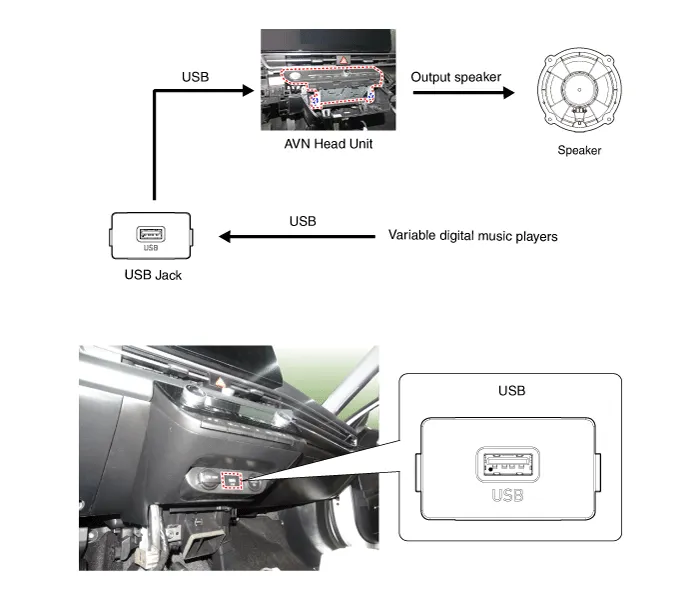
Hyundai Elantra (CN7): AVN System / USB Jack
Description and operation
| Description |
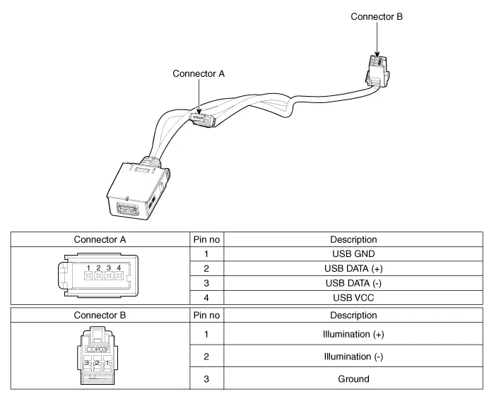
Schematic diagrams
| Circuit Diagram |
Repair procedures
| Removal |
| 1. | Disconnect the battery (-) terminals. |
| 2. | Remove the floor console assembly. (Refer to Body - "Floor Console Assembly") |
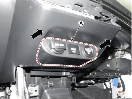
| 3. | Remove the UBS port assembly (A).
|
| 4. | Remove the avn head unit. (Refer to AVN System - "AVN(Audio Video Navigation) head unit") |
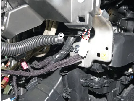
| 5. | Disconect the USB connector (A).
|

| 6. | Disconect the USB connector (B). [Display Audio only]
|
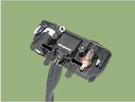
| 7. | Remove the USB jack (A) after releasing the fixed hooks.
|
| Installation |
| 1. | Connect the USB jack connector. |
| 2. | Install the USB jack. |
| 3. | Install the UBS port assembly. |
Repair procedures Inspection1.Troubleshooting for Speaker(1)Basic inspection of speakerInspect the sound from speaker after verifying that the speaker mounting screws is removed and the wiring connector is connected precisely to remove vibration transmitted from body trims and surrounding parts.
Repair procedures Inspection1.Disconnector the negative (-) battery terminal.2.Remove the overhead console lamp.(Refer to Body Electrical System - "Overhead Console Lamp")3.
Other information:
Hyundai Elantra (CN7) 2021-2026 Service Manual: Climate Control Air Filter
Description and operation Description The climate control air filter is located in the blower unit. It eliminates foreign materials and odor. The particle filter performs a role as an odor filter as well as a conventional dust filter to ensure comfortable interior environment.
Hyundai Elantra (CN7) 2021-2026 Service Manual: Heater Control Unit
Components and components location Component Location1. Heater control unitComponents[Connector A] Pin No Function Pin No Function 1Mode control actuator (Feedback)21Mode control actuator (Vent)2Intake actuator (Feedback)22Mode control actu
Categories
- Manuals Home
- Hyundai Elantra Owners Manual
- Hyundai Elantra Service Manual
- Driver assistance system
- Components and components location
- Drive Mode
- New on site
- Most important about car
