Hyundai Elantra (CN7): Engine Control System / Boost Pressure Sensor (BPS)
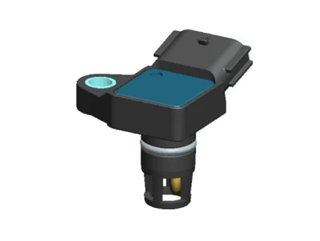
Description and operation
| Description |
Specifications
| Specification |
|
Pressure
[kPa (kgf/cm², psi)] |
Output Voltage (V)
[Vref = 5.0V] |
| 10 (0.10, 1.45) | 0.5 |
| 40 (0.40, 5.80) | 0.91 |
| 80 (0.81, 11.60) | 1.47 |
| 120 (1.22, 17.40) | 2.02 |
| 160 (1.63, 23.20) | 2.57 |
| 200 (2.03, 29.00) | 3.12 |
| 220 (2.24, 31.90) | 3.4 |
| 240 (2.44, 34.80) | 3.67 |
| 280 (2.85, 40.61) | 4.22 |
| 300 (3.05 43.51) | 4.5 |
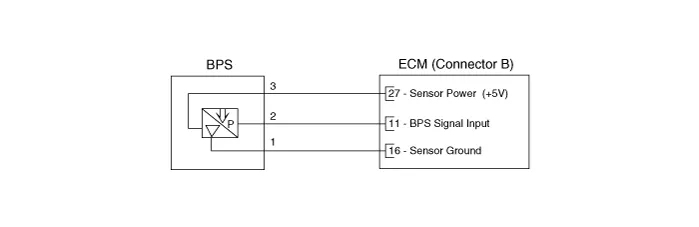
Schematic diagrams
| Circuit Diagram |
Repair procedures
| Inspection |
| 1. | Connect the diagnostic tool on the Data Link Connector (DLC). |
| 2. | Measure the BPS output voltage in IG ON and idle.
|
| Removal |
| 1. | Turn ignition switch OFF and disconnect the battery negative (-) terminal. |
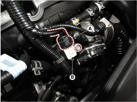
| 2. | Disconnect the boost pressure sensor connector (A). |
| 3. | Remove the sensor (B) after remove the mounting bolt.
|
| Installation |
|

| 1. | Install in the reverse order of removal. |
Schematic diagrams ECM Terminal And Input/Output signalECM Terminal FunctionConnector [A] Pin No Description 1Fuel Pressure Control Valve (FPCV) [High] control2Integrated Thermal Mangement Module (ITM) Motor (+)3Integrated Thermal Mangement Module (ITM) Motor (-)4-5Engine Coolant Temperature Sensor (ECTS) #1 (Ground)6-7Engine Coolant Temperature Sensor (ECTS) #2 (Ground)8-9Rail Pressure Sensor (RPS) (Ground)10-11Manifold Absolute Pressure Sensor (MAPS) (Ground)12Electric WGT Control Actuator (EWGA) (Ground)13-14Oil Pressure & Temperature Sensors (OPTS) (Ground)15-16-17A/C Pressure Transducer (APT) (Ground)18Sensor Power (+5V) (Camshaft Position Sensor (CMPS) [Bank 1 / Intake, Exhaust])19Sensor Power (+5V) (MAPS, CKPS)20Sensor Power (+5V) (OPS, ETC, RPS)21Sensor Ground (Throttle Position Sensor (TPS))22-23-24Sensor Shield (Knock Sensor (KS))25-26Ignition Coil (Cylider #3) Control27-28-29-30-31-32-33-34-35Integrated Thermal Mangement Module (ITM) Motor (Ground)36-37Camshaft Position Sensor (CMPS) [Bank 1 / Intake] Signal38-39Electric WGT Control Actuator (EWGA) Signal40Sensor Power (+5V) (EWGA)41Sensor Power (+5V) (APS #1)42Sensor Power (+5V) (APT)43Injector (Cylinder #3) [+] Control44Injector (Cylinder #2) [+] Control45-46-47CCP-CAN (High)48Ignition Coil (Cylider #1) Control49-50-51-52-53-54-55-56-57-58-59-60Camshaft Position Sensor (CMPS) [Bank 1 / Exhaust] (Ground)61-62-63Engine RPM Output64Injector (Cylinder #1) [+] Control65Injector (Cylinder #4) [+] Control66Injector (Cylinder #3) [-] Control67Injector (Cylinder #4) [-] Control68Ignition Coil (Cylider #2) Control69CCP-CAN (Low)70Camshaft Position Sensor (CMPS) [Bank 1 / Exhaust] Signal71Crankshaft Position Sensor (CKPS) (Ground)72Ignition Lock Switch Control73Oil Pressure Sensor (OPS) Signal74Intake Air Temperature Sensor (IATS) Signal75Engine Coolant Temperature Sensor (ECTS) #1 Signal76Engine Coolant Temperature Sensor (ECTS) #2 Signal77-78-79Throttle Position Sensor (TPS) 2 Signal80Rail Pressure Sensor (RPS) Signal81-82Integrated Thermal Mangement Module (ITM) Motor Signal83-84A/C Pressure Transducer (APT) Signal85-86Injector (Cylinder #2) [-] Control87Injector (Cylinder #1) [-] Control88Fuel Pressure Control Valve (FPCV) [Low] control89-90Ignition Coil (Cylider #4) Control91Crankshaft Position Sensor (CKPS) Signal92Integrated Body Control Unit (IBU) External Wake-Up Signal93Heated Oxygen Sensor (HO2S) [Bank 1 / Sensor 2] (Ground)94-95Heated Oxygen Sensor (HO2S) [Bank 1 / Sensor 1] Signal96-97Oil Temperature Sensor (OTS) Signal98Throttle Position Sensor (TPS) 1 Signal99-100-101Manifold Absolute Pressure Sensor (MAPS) Signal102Camshaft Position Sensor (CMPS) [Bank 1 / Intake] (Ground)103-104Knock Sensor (KS) Signal105Knock Sensor (KS) (Ground)Connector [B] Pin No Description 1Chassis Ground2Chassis Ground3Battery power (B+) (Battery)4Chassis Ground5Battery power (B+) (Main Relay)6Battery power (B+) (Main Relay)7-8-9Sensor Power (+5V) (ITM Motor)10Sensor Power (+5V) (APS #2)11Boost Pressure Sensor (BPS) Signal Input12Accelerator Position Sensor (APS #2) (Ground)13Accelerator Position Sensor (APS #1) (Ground)14-15-16Boost Pressure Sensor (BPS) (Ground)17Fuel Level Sender (FLS) Signal18Accelerator Position Sensor (APS #2) Signal19-20-21-22Rail Pressure Sensor (RPS) Control23Cooling Fan Relay [PMW] Control24EWGA DC Motor Control (+)25EWGA DC Motor Control (-)26Ignition Switch Signal Input27Sensor Power (+5V) (BPS)28-29-30Brake [Test] Switch Signal Input31Brake [Light] Switch Signal Input32Accelerator Position Sensor (APS #1) Signal33-34-35Engine Start Switch Signal Input36-37Fuel Pump Relay Control [Without Smart Key] Control38-39-40Variable Oil Pump Valve Control41ETC Motor [+] Control42ETC Motor [-] Control43-44-45P-CAN (Low)46-47-48Clutch Switch Control49Wiper Switch Input50-51Start Relay (Low) Control 52-53-54Electric load Signal Input [Defrost]55-56-57-58-59-60Battery power (B+) (Battery)61LIN Communication Signal Input62P-CAN (High)63-64Heated Oxygen Sensor (HO2S) [Bank 1 / Sensor 1] VS-/IP- (Virtual Ground)65Heated Oxygen Sensor (HO2S) [Bank 1 / Sensor 1] Rc/Rp (Pumping Cell Current)66Heated Oxygen Sensor (HO2S) [Bank 1 / Sensor 1] Rc (Adjust Resistance)67Heated Oxygen Sensor (HO2S) [Bank 1 / Sensor 1] VS+ (NERNST Cell Current)68-69-70-71Start Relay (High) Control72-73-74Engine Control Relay Control75Heated Oxygen Sensor (HO2S) [Bank 1 / Sensor 1] Heater Control76Heated Oxygen Sensor (HO2S) [Bank 1 / Sensor 2] Heater Control77Vehicle Speed Input (IBU, VDC Moduel)78CCP-CAN (High)79CCP-CAN (Low)80-81-82-83Purge Control Solenoid Valve (PCSV) Control84Fuel Pump Relay Control [With Smart Key] Control85-86-87Integrated Body Control Unit (IBU) (IMMO, Data Line)88-89-90-91-92Variable Force Solenoid (VFS) [Bank 1 / Intake] Control93Variable Force Solenoid (VFS) [Bank 1 / Exhaust] Control Repair procedures Removal1.
Description and operation DescriptionThe Electronic Throttle Control (ETC) System consists of a throttle body with an integrated control motor and throttle position sensor (TPS).
Other information:
Hyundai Elantra (CN7) 2021-2026 Service Manual: A/C Pressure Transducer
Description and operation DescriptionThe A/C Pressure Transducer (APT) converts the pressure value of high pressure line into voltage value after measuring it. By converted voltage value, engine ECU controls the cooling fan by operating it high speed or low speed.
Hyundai Elantra (CN7) 2021-2026 Service Manual: Description and operation
D
Categories
- Manuals Home
- Hyundai Elantra Owners Manual
- Hyundai Elantra Service Manual
- Specifications
- Engine Mechanical System
- Maintenance
- New on site
- Most important about car
