
Hyundai Elantra (CN7): Audio / Audio Remote Control
Components and components location
| Components |
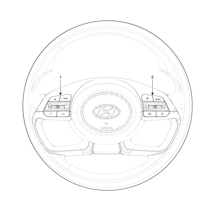
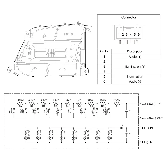
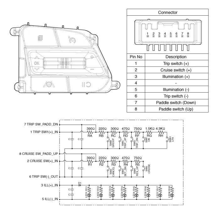
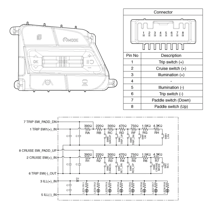
| 1. Left Remote Control Switch (Audio + Bluetooth) | 2. Right Remote Control Switch (Cruise + Trip) |
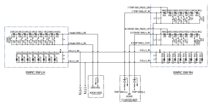
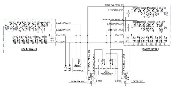
Schematic diagrams
| Circuit Diagram |
| [Without paddle shift] |
| [With paddle shift] |




Repair procedures
| Inspection |
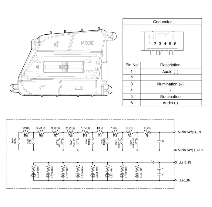
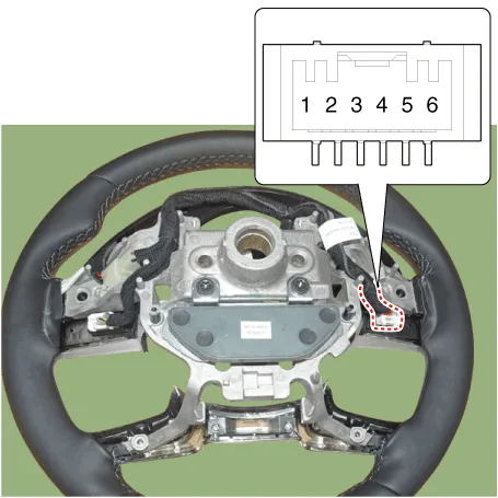
| 1. | Check for resistance between terminals in each switch position (LH).
[LH : Audio + Hands free]
|
| 2. | Check for resistance between terminals in each switch position (RH).
[Cruise]
[Trip]
|
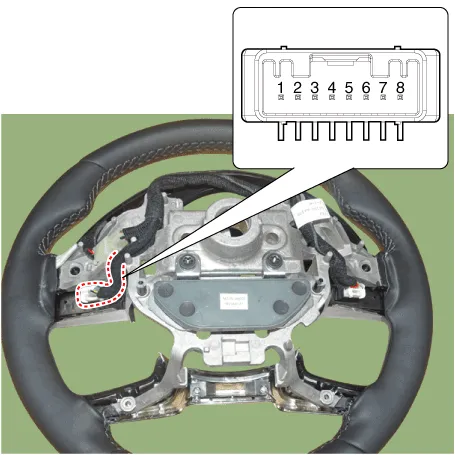
| Removal |
| 1. | Disconnect the negative (-) battery terminal. |
| 2. | Remove the steering wheel assembly. (Refer to Steering System - "Steering Wheel") |
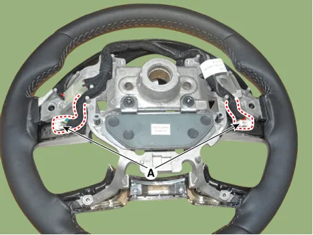
| 3. | Remove the steering back cover (A).
|

| 4. | Remove the steering remote control connector (A).
|
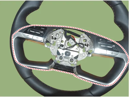
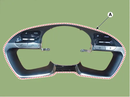
| 5. | Remove the steering remote control switch (A) after loosening the screws.
|
| Installation |
| 1. | Install the steering wheel remote control after connecting the connector. |
| 2. | Install the steering wheel. |
| 3. | Connect the negative (-) battery terminal. |
Repair procedures InspectionGlass Antenna Test1.Wrap aluminum foil (A) around the tip of the tester probe (B) as shown.2.Touch one tester probe to the glass antenna terminal (A) and move the other tester probe along the antenna wires to check that continuity exists.
Description and operation DescriptionThe multimedia jack on the console upper cover is for customers who like to listen to external portable music players like the MP3 etc.
Other information:
Hyundai Elantra (CN7) 2021-2026 Service Manual: Mode Control Actuator
Description and operation DescriptionThe mode control actuator is located at the heater unit.It adjusts the position of the mode door by operating the mode control actuator based on the signal of the A/C control unit. Pressing the mode select switch makes the mode control actuator shift in order of Vent → Bi-Level → Floor → Mix.
Hyundai Elantra (CN7) 2021-2026 Service Manual: Front Radar Unit
Components and components location Components Location1. Front rader unit Specifications Specification Item Specification Power supply (V)12Operation voltage (V)9 - 16 Schematic diagrams Circuit DiagramTerminal function Pin No Te
Categories
- Manuals Home
- Hyundai Elantra Owners Manual
- Hyundai Elantra Service Manual
- Body (Interior and Exterior)
- Specifications
- Brake bleeding procedures
- New on site
- Most important about car
