Hyundai Elantra (CN7): Audio / USB Jack
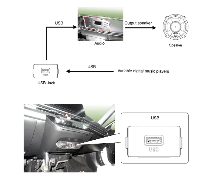
Description and operation
| Description |
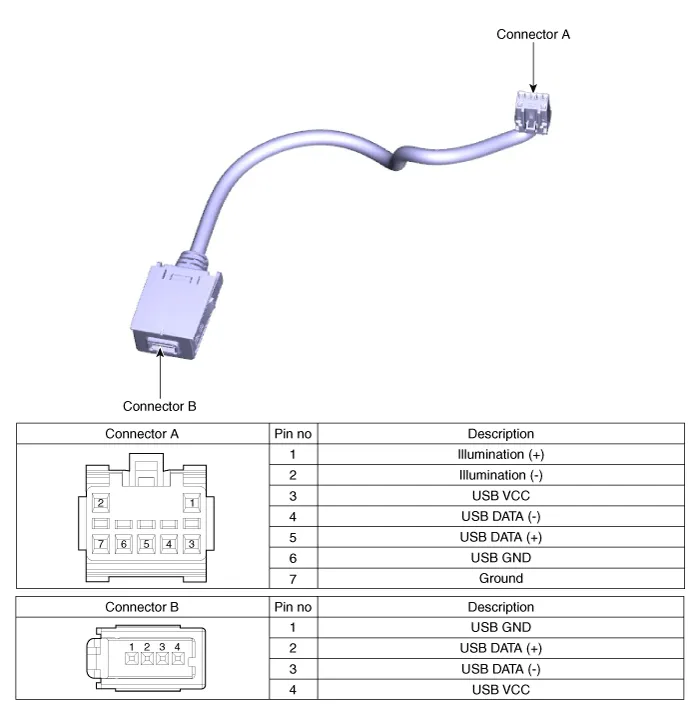
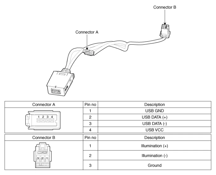
Schematic diagrams
| Circuit Diagram |
Repair procedures
| Removal |
| 1. | Disconnect the battery (-) terminals. |
| 2. | Remove the floor console assembly. (Refer to Body - "Floor Console Assembly") |
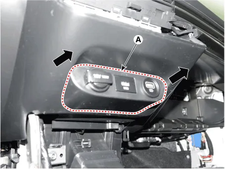
| 3. | Remove the USB port assembly (A).
|
| 4. | Remove the audio unit. (Refer to Audio - "Audio Unit") |
| 5. | Disconect the USB connector (A).
|

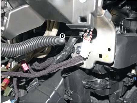
| 6. | Disconect the USB connector (B). [Display Audio only]
|
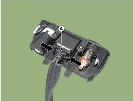
| 7. | Remove the USB jack (A) after releasing the fixed hooks.
|
| Installation |
| 1. | Connect the USB jack connector. |
| 2. | Install the audio unit. |
| 3. | Install the USB jack. |
| 4. | Install the USB port assembly. |
Components and components location Components1. Left Remote Control Switch (Audio + Bluetooth)2. Right Remote Control Switch (Cruise + Trip) Schematic diagrams Circuit Diagram[Without paddle shift][With paddle shift][Audio + B/Tooth][Audio + B/Tooth + Voice][Trip][Trip / Cruise][Trip + Cruise + LFA)[Trip + Cruise + LFA + MSLA)[Trip + Smart Cruise + LFA)[Trip + Smart Cruise + LFA + MSLA) Repair procedures Inspection1.
Other information:
Hyundai Elantra (CN7) 2021-2026 Service Manual: Condenser
Components and components location Components Location[General type]1. Condenser[N Line]1. Condenser Repair procedures Inspection1.Check the condenser fins for clogging and damage. If clogged, clean them with water, and blow them with compressed air.
Hyundai Elantra (CN7) 2021-2026 Service Manual: Blower Resistor (Manual)
Repair procedures Inspection1.Measure the resistance between the terminals.2.The measured resistance is not within specification, the blower resistor must be replaced. (After removing the resistor)Replacement1.Disconnect the negative (-) battery terminal.
Categories
- Manuals Home
- Hyundai Elantra Owners Manual
- Hyundai Elantra Service Manual
- General Tightening Torque Table. General information
- Body Electrical System
- Repair procedures
- New on site
- Most important about car
