Hyundai Elantra (CN7): Brake System / Brake Line
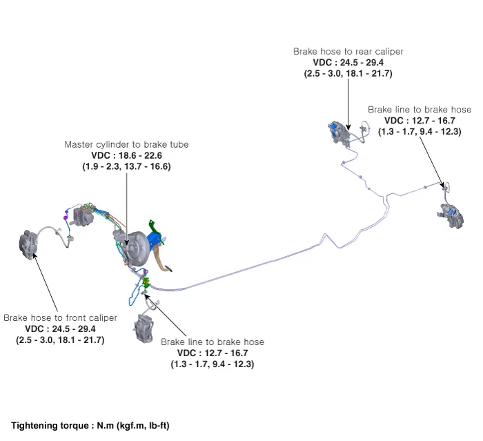
Components and components location
| Components |
Repair procedures
| Removal |
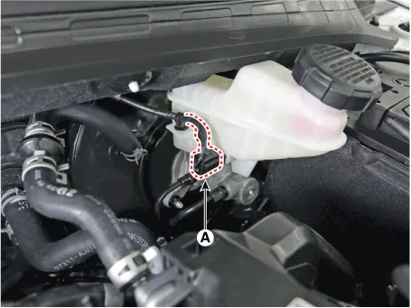
| 1. | Disconnect the brake fiuid level switch connector, and remove the reservoir cap. |
| 2. | Remove the brake fluid from the master cylinder reservior with a syringe.
|

| 3. | Remove the brake tube after loosening the flare nuts from the ESC, master cylinder and brake tube connector.
|
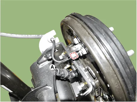
| 1. | Disconnect the brake fluid level sensor connector (A).
|
| 2. | Remove the brake fluid from the master cylinder reservior with a syringe.
|

| 3. | Loosen the wheel nuts slightly. Raise the vehicle, and make sure it is securely supported. |
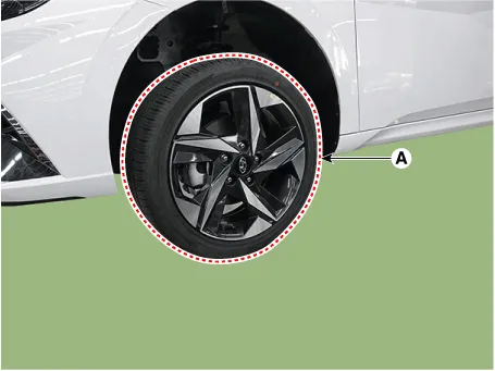
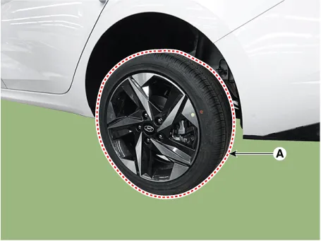
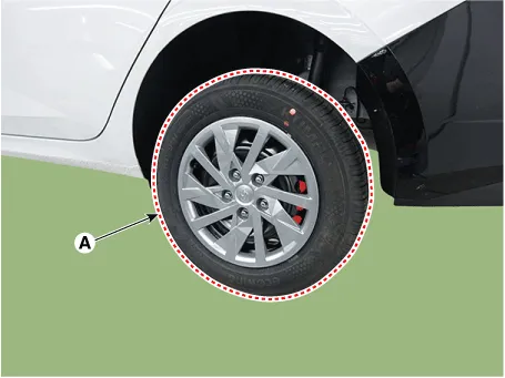
| 4. | Remove the front wheel and tire (A) from the front hub.
|
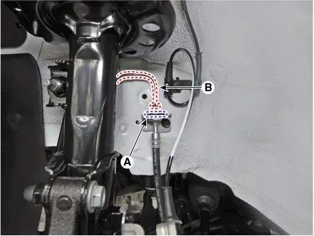
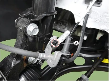
| 5. | Remove the brake hose clip (A). |
| 6. | Disconnect the tube after loosening the tube flare nut (B).
|
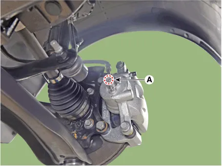
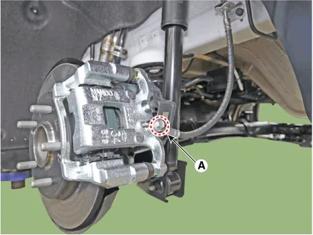
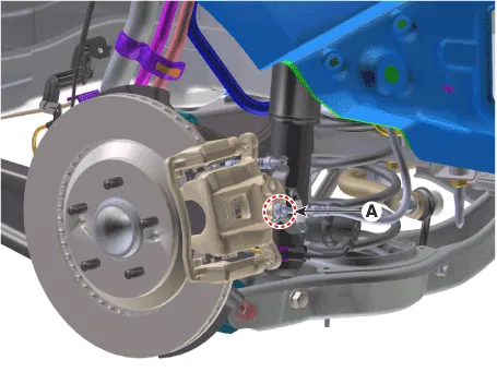
| 7. | Remove the brake hose bracket mounting bolt (A).
|
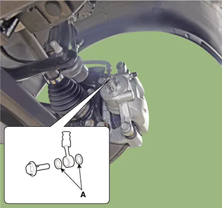
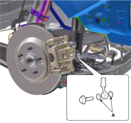
| 8. | Remove the hose after loosening the brake hose bolt (A) from the caliper.
|
| 1. | Disconnect the brake fluid level sensor connector (A).
|
| 2. | Remove the brake fluid from the master cylinder reservior with a syringe.
|
| 3. | Loosen the wheel nuts slightly. Raise the vehicle, and make sure it is securely supported. |
| 4. | Remove the front wheel and tire (A) from the front hub.
|
| 5. | Remove the brake hose clip (A). |
| 6. | Disconnect the tube after loosening the tube flare nut (B).
|
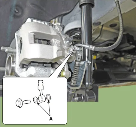
| 7. | Remove the hose after loosening the brake hose bolt (A) from the caliper.
[Rear torsion beam parking cable type]
[Rear torsion beam EPB type]
[Rear multi link parking cable type]
[Rear multi link EPB type]
|

| 1. | Disconnect the brake fluid level sensor connector (A).
|
| 2. | Remove the brake fluid from the master cylinder reservoir with a syringe.
|
| 3. | Loosen the wheel nuts slightly. Raise the vehicle, and make sure it is securely supported. |
| 4. | Remove the rear wheel and tire (A) from the rear hub.
|
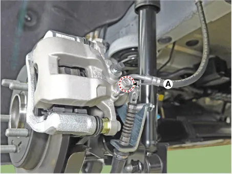
| 5. | Loosen the tube flare nut (A). |
| 6. | Loosen the brake hose bracket bolt (B).
|

| 7. | Loosen the brake hose bracket bolt (A).
|
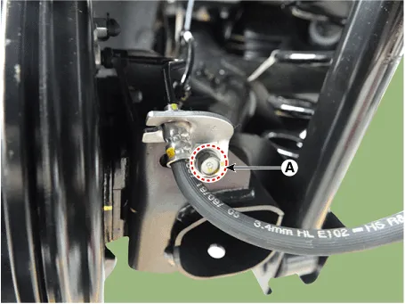
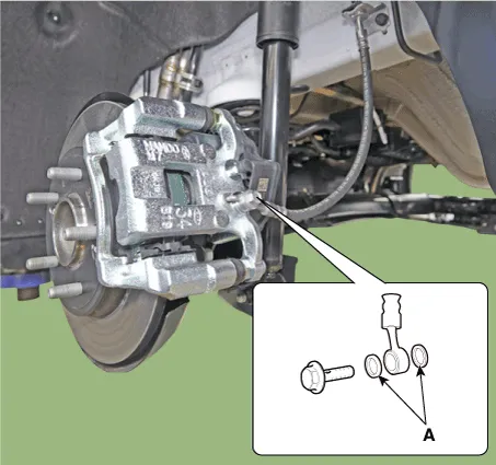
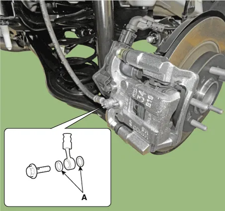
| 8. | Remove the brake hose after loosening the hose flare nut (A).
|
| Inspection |
| 1. | Check the brake tubes for cracks, crimps and corrosion. |
| 2. | Check the brake tube flare nuts for damage and fluid leakage. |
| Installation |
| 1. | To install, reverse the removal procedures.
|
| 2. | After installation, bleed the brake system. (Refer to Brake System - "Brake Bleeding Prcoedures") |
Components and components location Components1. Reservoir cap2. Reservoir3. Brake fluid lever sensor4. Master cylinder5. Brake booster6. Push road Repair procedures Removal[LHD]1.
Specifications Specification Fluid Type DOT 4 Reservoir Quantity (cc) Total VolumeA + B + C + D + E + F405 ± 20MAX LEVEL A + B + C + D + E 392 ± 20ON LEVELB + C + D + E155 ± 10MIN LEVELC + D + E107 ± 10PART LEVELDPri : 44 ± 5ESec : 37 ± 5CLUTCH LEVEL F 13 ± 5 Repair procedures Replacement1.
Other information:
Hyundai Elantra (CN7) 2021-2026 Service Manual: Components and components location
C
Hyundai Elantra (CN7) 2021-2026 Service Manual: Troubleshooting
Trouble Symptom ChartsTrouble Symptom 1Trouble Symptom 2 Trouble symptom Probable cause Remedy The set vehicle speed varies greatly upward or downward"Surging" (repeated alternating acceleration and deceleration) occurs after settingMalfunction of the vehicle speed se
Categories
- Manuals Home
- Hyundai Elantra Owners Manual
- Hyundai Elantra Service Manual
- Engine Control / Fuel System
- Front Bumper
- Suspension System
- New on site
- Most important about car
