Hyundai Elantra (CN7): Brake System / Master Cylinder
Components and components location
| Components |
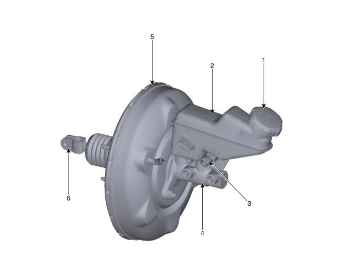
| 1. Reservoir cap 2. Reservoir 3. Brake fluid lever sensor | 4. Master cylinder 5. Brake booster 6. Push road |
Repair procedures
| Removal |
| 1. | Turn ignition switch OFF and disconnect the negative (-) battery cable. |
| 2. | Remove the brake fluid from the master cylinder reservior with a syringe.
|

| 3. | Remove the battery. (Refer to Engine Electrical System - "Battery") |
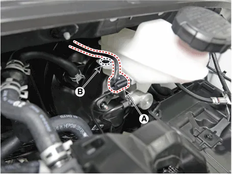
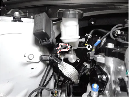
| 4. | Disconnect the brake fluid level sensor connector (A) and then removing the wiring clip (B).
|
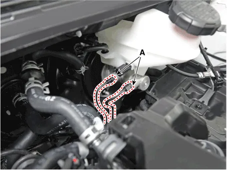
| 5. | Separate the brake tube (A) from the master cylinder by loosening the tube flare nut.
|
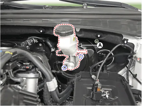
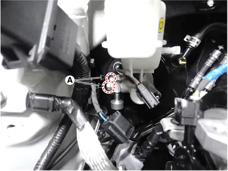
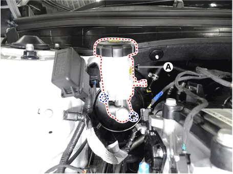
| 6. | Remove the master cylinder (A) after loosening the master cylinder nuts.
|
| 1. | Turn ignition switch OFF and disconnect the negative (-) battery cable. |
| 2. | Remove the brake fluid from the master cylinder reservior with a syringe.
|
| 3. | Disconnect the brake fluid level sensor connector (A).
|
| 4. | Remove the brake tube after loosening the mounting bolts (A).
|
| 5. | Remove the master cylinder (A) after loosening the mounting nuts.
|
| Installation |
| 1. | To install, reverse the removal procedure.
|

| 2. | After installation, bleed the brake system. (Refer to Brake System - "Brake Bleeding Prcoedures") |
| 3. | Check the brake oil leakage and pedal operating condition. |
Components and components location Components1. Reservoir cap2. Reservoir3. Brake fluid lever sensor4. Master cylinder5. Brake booster6. Push road Repair procedures Brake Booster Operating Test1.
Components and components location Components Repair procedures RemovalBrake Tube [Engine Room]1.Disconnect the brake fiuid level switch connector, and remove the reservoir cap.
Other information:
Hyundai Elantra (CN7) 2021-2026 Service Manual: General safety information and caution
Instructions (R-134a)When Handling Refrigerant1.R-134a liquid refrigerant is highly volatile. A drop on the skin of your hand could result in localized frostbite. When handling the refrigerant, be sure to wear gloves. 2.It is standard practice to wear goggles or glasses to protect your eyes, and gloves to protect your hands.
Hyundai Elantra (CN7) 2021-2026 Service Manual: Compressor
Description and operation DescriptionThe compressor is the power unit of the A/C system.It is located on the side of engine block and driven by a V-belt of the engine.The compressor changes low pressure and low temperature refrigerant gas into high pressure and high temperature refrigerant gas.
Categories
- Manuals Home
- Hyundai Elantra Owners Manual
- Hyundai Elantra Service Manual
- Front Radar Unit
- Integrated Thermal Management Module (ITM)
- Drive Mode
- New on site
- Most important about car
