Hyundai Elantra (CN7): Clutch System / Clutch Tube
Components and components location
| Components and Components Location |
| [Gasoline 1.6 MPI / Gasoline 2.0 MPI] |
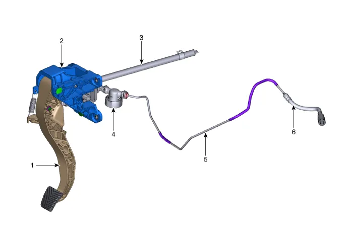
| 1. Clutch pedal arm 2. Clutch pedal assembly 3. Reservoir hose | 4. Regulator 5. Cluch tube 6. Clutch hose |
| [Gasoline 1.6 T-GDI] |
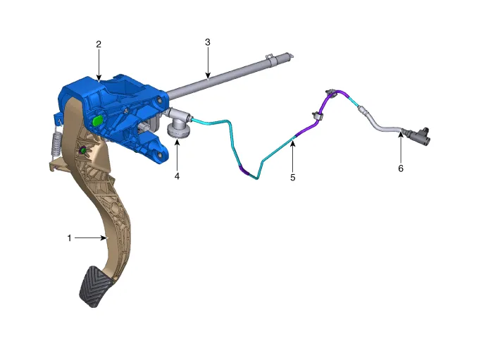
| 1. Clutch pedal arm 2. Clutch pedal assembly 3. Reservoir hose | 4. Regulator 5. Cluch tube 6. Clutch hose |
Repair procedures
| Removal |
| 1. | Remove the air cleaner and air duct. (Refer to Engine Mechanical System - "Air Cleaner") |
| 2. | Remove the battery and battery tray. (Refer to Engine Electrical System - "Battery") |
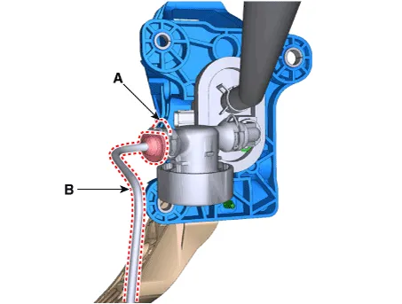
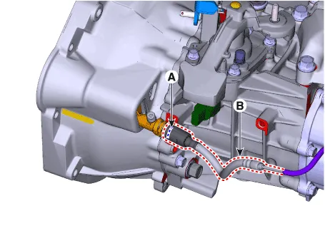
| 3. | Pull the snap pin (A) and then separate the clutch tube (B). [Gasoline 1.6 MPI / Gasoline 2.0 MPI]
|

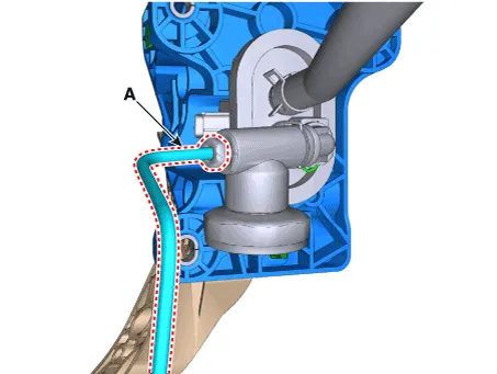
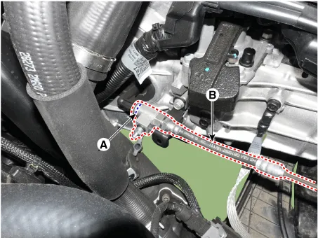
| 4. | Loosen the flare nut and then separate the clutch tube (A). [Gasoline 1.6 T-GDI]
|
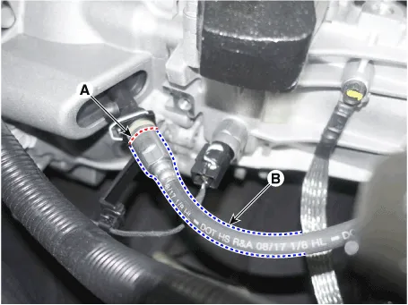
| 5. | Remove the snap pin (A) and then separate the clutch hose & tube (B). [Gasoline 1.6 MPI]
[Gasoline 1.6 T-GDI]
[Gasoline 2.0 MPI]
|
| 6. | Remove the clutch hose & tube from the vehicle. |
| Installation |
| 1. | To install, reverse the removal procedures. |
| 2. | Perform bleeding air procedure in concecntric slave cylinder after pouring the brake fluid (Refer to Clutch System - "Concentric Slave Cylinder Assembly") |
Components and components location Components and Components Location[Gasoline 1.6 MPI / Gasoline 2.0 MPI]1. Clutch pedal arm2. Clutch pedal assembly3.
Components and components location Components1. Clutch pedal arm2. Clip3. Push rod pin4. Clutch pedal assembly5. Clutch master cylinder6. Clip Repair procedures Removal1.
Other information:
Hyundai Elantra (CN7) 2021-2026 Service Manual: Ignition Switch Assembly. Repair procedures
Repair procedures Replacement1.Disconnect the negative (-) battery terminal.2.Remove the crash pad lower panel.(Refer to Body - "Crash Pad")3.Remove the steering column upper & Lower shroud.4.Remove the ignition switch and disconnecting the Key Warning / immobilizer connector.
Hyundai Elantra (CN7) 2021-2026 Service Manual: Components and components location
C
Categories
- Manuals Home
- Hyundai Elantra Owners Manual
- Hyundai Elantra Service Manual
- Troubleshooting
- Integrated Thermal Management Module (ITM)
- Front Radar Unit
- New on site
- Most important about car

Copyright © 2026 www.helantra7.com - 0.0171