Hyundai Elantra (CN7): Clutch System / Regulator
Components and components location
| Components and Components Location |
| [Gasoline 1.6 MPI / Gasoline 2.0 MPI] |
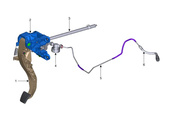
| 1. Clutch pedal arm 2. Clutch pedal assembly 3. Reservoir hose | 4. Regulator 5. Cluch tube 6. Clutch hose |
| [Gasoline 1.6 T-GDI] |
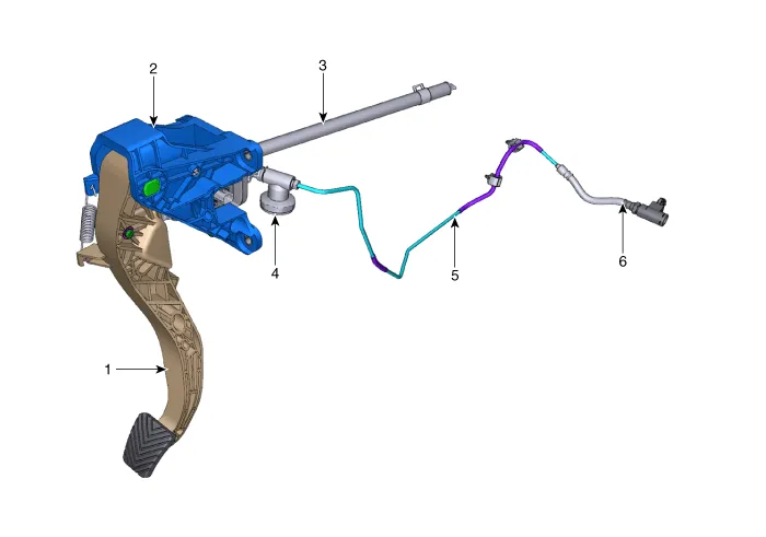
| 1. Clutch pedal arm 2. Clutch pedal assembly 3. Reservoir hose | 4. Regulator 5. Cluch tube 6. Clutch hose |
Repair procedures
| Removal |
| 1. | Remove the air duct and air cleaner assembly. (Refer to Engine Mechanical System - "Air Cleaner") |
| 2. | Remove the battery and battery tray. (Refer to Engine Electrical System - "Battery") |
| 3. | Pull the snap pins (A) and then removing the regulator (B). [Gasoline 1.6 MPI / Gasoline 2.0 MPI]
|

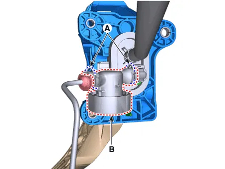
| 4. | Pull the snap pin (B) after separate the clutch tube (A) and Remove the regulator (C). [Gasoline 1.6 T-GDI]
|

| Installation |
| 1. | To install, reverse the removal procedures.
|

| 2. | After be equipped, perform bleeding air procedure in concentric slave cylinder after pouring the brake fluid. (Refer to Clutch System - "Concentric Slave Cyilnder Assembly") |
| Inspection |
| 1. | Check the clutch tube for fluid leakage. |
| 2. | Check the clutch tube for strain and damage. |
Components and components location Components1. Clutch pedal arm2. Clip3. Push rod pin4. Clutch pedal assembly5. Clutch master cylinder6. Clip Repair procedures Removal1.
Components and components location Components and Components Location[Gasoline 1.6 MPI / Gasoline 2.0 MPI]1. Clutch pedal arm2. Clutch pedal assembly3.
Other information:
Hyundai Elantra (CN7) 2021-2026 Service Manual: Components and components location
C
Hyundai Elantra (CN7) 2021-2026 Service Manual: Troubleshooting
TroubleshootingProblem Symptoms TableBefore replacing or repairing air conditioning components, first determine if the malfunction is due to the refrigerant charge, air flow or compressor.Use the table below to help you find the cause of the problem. The numbers indicate the priority of the likely cause of the problem.
Categories
- Manuals Home
- Hyundai Elantra Owners Manual
- Hyundai Elantra Service Manual
- Engine Control / Fuel System
- Repair procedures
- Front Radar Unit
- New on site
- Most important about car

Copyright © 2026 www.helantra7.com - 0.0125