Hyundai Elantra (CN7): Head Lamp Leveling Device / Components and components location
| Component Location |
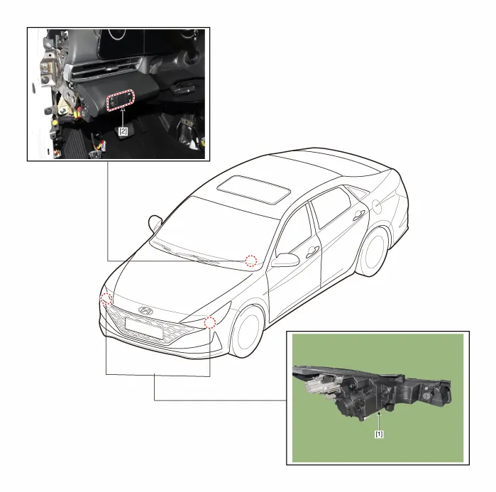
| 1. Head lamp leveling actuator | 2. Head lamp leveling switch |
Schematic diagrams Schematic Diagrams Repair procedures Replacement1.Disconnect the negative (-) battery terminal.2.Remove the crash pad lower panel (A).
Other information:
Hyundai Elantra (CN7) 2021-2025 Service Manual: Photo Sensor
Description and operation Description 1.The photo sensor is located at the center of the defrost nozzles.2.The photo sensor contains a photovoltaic (sensitive to sunlight) diode. The solar radiation received by its light receiving portion, generates an electromotive force in proportion to the amount of radiation received which is transferred to
Hyundai Elantra (CN7) 2021-2025 Service Manual: Repair procedures
Inspection1.Check for resistance between terminals in each switch position (LH).[LH : Audio + Hands free] Switch Resistance (±5%) SEEK Up430 ΩSEEK Down1.11 kΩMODE2.11 kΩMUTE3.11 kΩVolume (+)4.
Categories
- Manuals Home
- Hyundai Elantra Owners Manual
- Hyundai Elantra Service Manual
- Recommended Lubricants and Capacities
- Maintenance
- Tire Specification and Pressure Label, Engine Number
- New on site
- Most important about car