Hyundai Elantra (CN7): ABS(Anti-Lock Brake System) / ESC (Electronic Stability Control) Module
Hyundai Elantra (CN7) 2021-2026 Service Manual / Brake System / ABS(Anti-Lock Brake System) / ESC (Electronic Stability Control) Module
Components and components location
| Components |
[LHD]
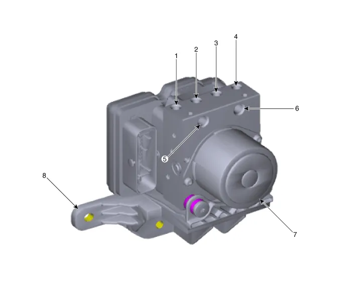
| 1. Front - right (FR) 2. Rear - left (RL) 3. Rear - right (RR) 4. Front - left (FL) | 5. MC2 6. MC1 7. ABS control module (HECU) 8. Bracket |
[RHD]
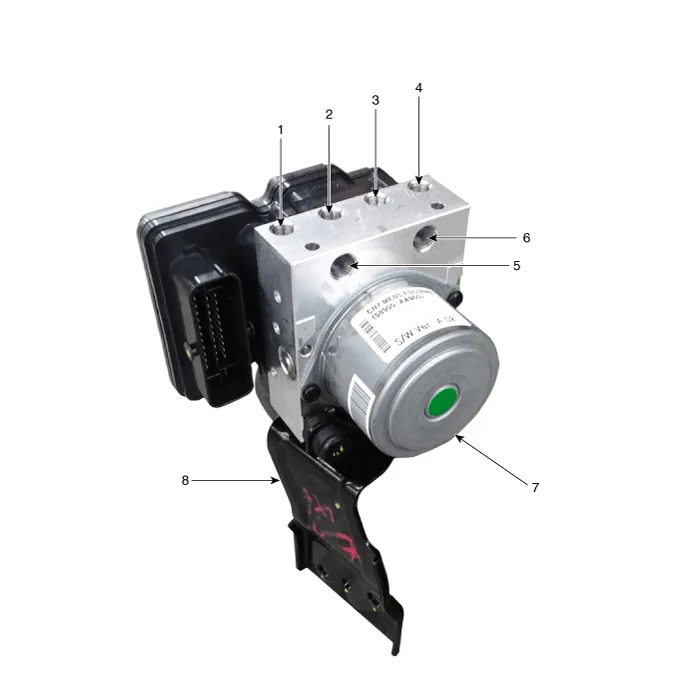
| 1. Front - right (FR) 2. Rear - left (RL) 3. Rear - right (RR) 4. Front - left (FL) | 5. MC2 6. MC1 7. ABS control module (HECU) 8. Bracket |
Repair procedures
| Removal |
[LHD]
| 1. | Turn ignition switch OFF and disconnect the negative (-) battery cable. |
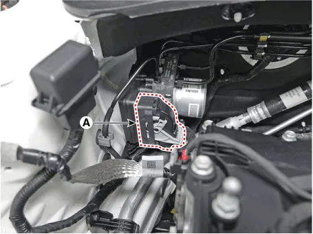
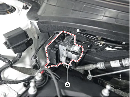
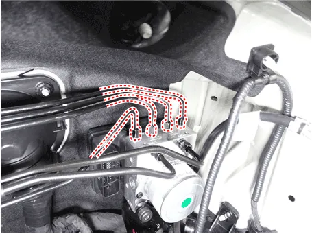
| 2. | Pull up the lock of the HECU connector and then disconnect the connector (A).
|
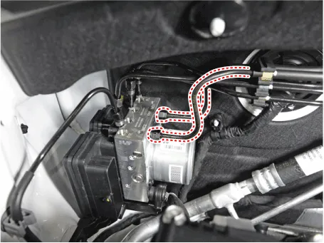
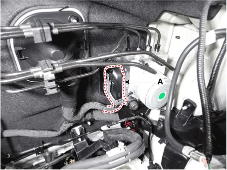
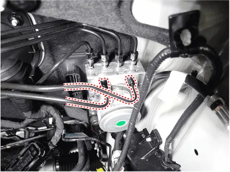
| 3. | Separate the brake tubes from the HECU by unlocking the nuts (6-ea) couterclockwise using a spanner.
|
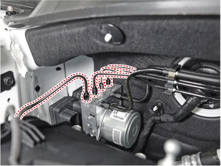
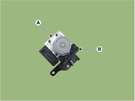
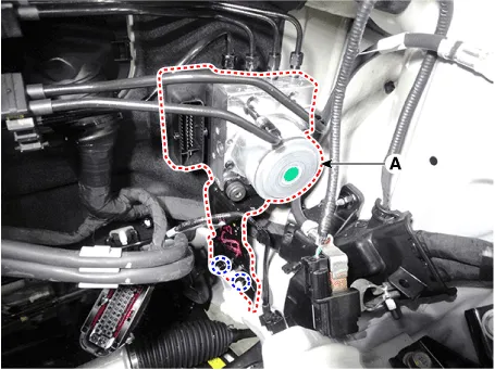
| 4. | Loosen the ABS control module mounting nut and then remove the ABS control module (A) from the vehicle.
|
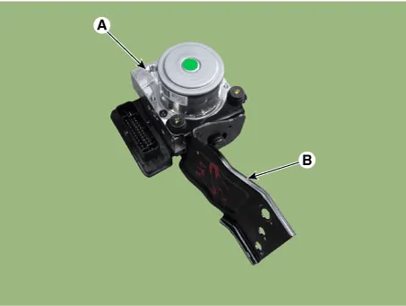
| 5. | Separate the bracket (B) after remove the mounting bolt from the HECU (A).
|
[RHD]
| 1. | Turn ignition switch OFF and disconnect the negative (-) battery cable. |
| 2. | Remove the battery and battery tray. (Refer to Engine Electrical System - "Battery") |
| 3. | Pull up the lock of the HECU connector and then disconnect the connector (A).
|
| 4. | Separate the brake tubes from the HECU by unlocking the nuts (6-ea) couterclockwise using a spanner.
|
| 5. | Loosen the ABS control module mounting nut and then remove the ESC control module (A) from the vehicle.
|
| 6. | Separate the bracket (B) after remove the mounting bolt from the HECU (A).
|
| Installation |
| 1. | To install, reverse the removal procedure. |
| 2. | After installation, bleed the brake system. (Refer to Brake System - "Brake Bleeding Prcoedures") |
| Adjustment |
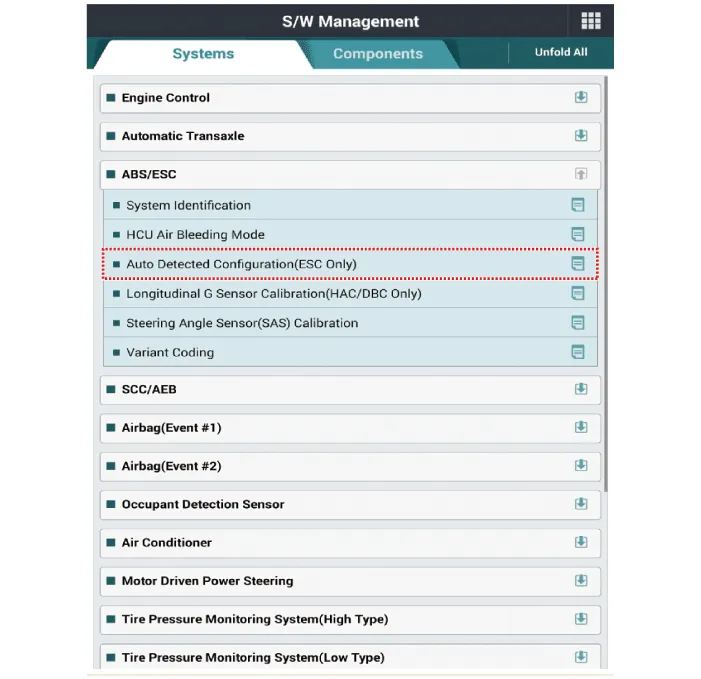
Perform diagnostic procedure by using diagnostic device as shown below.
| 1. | Connect self-diagnosis connector (16pins) located under the driver side crash pad to self-diagnosis device, and then turn the self-diagnosis device after key is ON. |
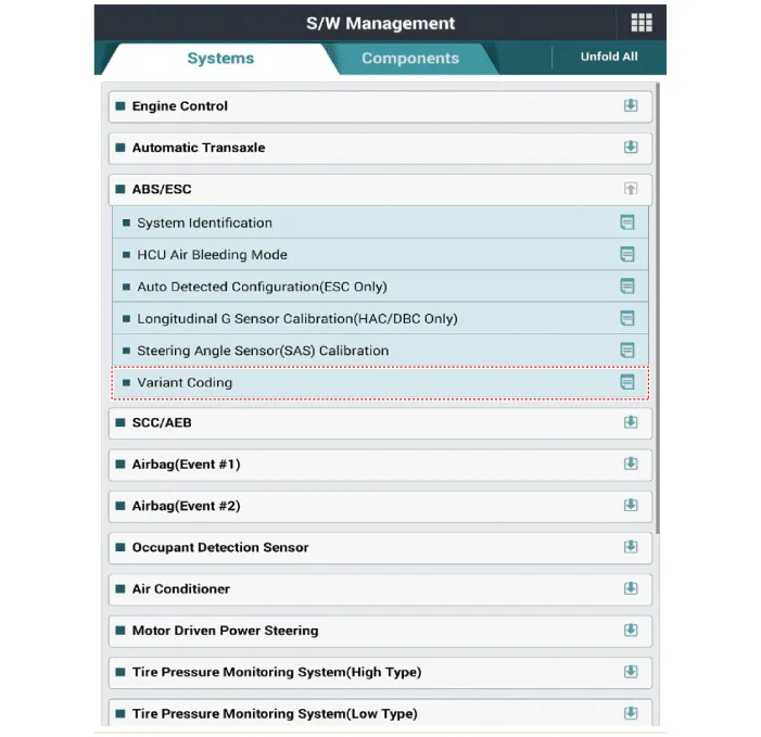
| 2. | Select the "vehicle model" and "ESP/ESC" on GDS vehicle selection screen, then select OK. [Variant Code Reset]
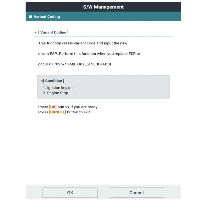
[Variant Coding]
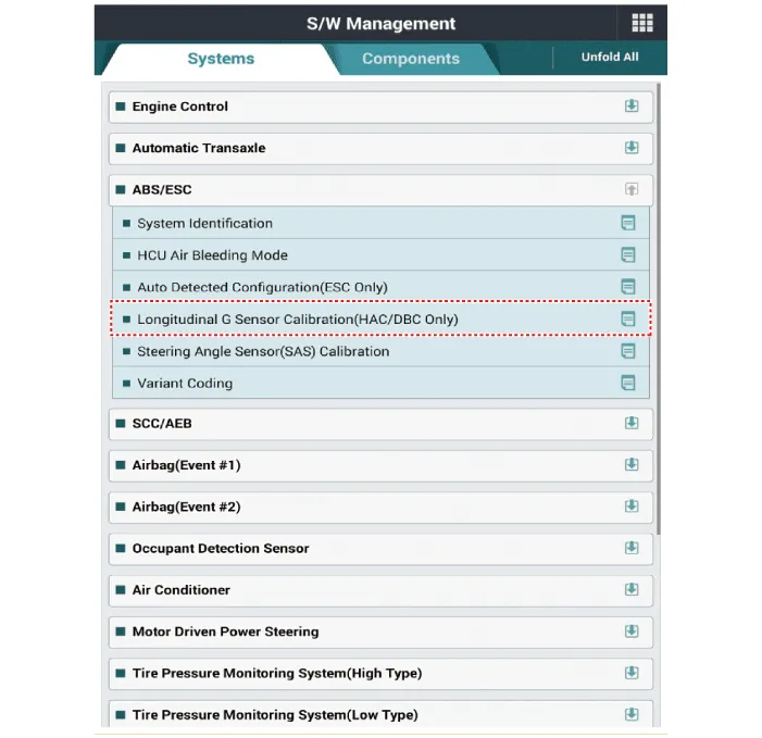
[Longitudinal G Sensor Calibration]
|
Terminal Function Pin No Description Current (AMPS) Resistance (mΩ) Remark 1POS.
Components and components location Components1. Front wheel speed sensor2. Front wheel speed sensor connector Repair procedures Removal1.Turn ignition switch OFF and disconnect the negative (-) battery cable.
Other information:
Hyundai Elantra (CN7) 2021-2026 Service Manual: Components and components location
C
Hyundai Elantra (CN7) 2021-2026 Service Manual: Parking Distance Warning (PDW)
Description and operation Description• PDW consists of 8 sensors (front : 4 units, rear : 4 units) that are used to detect obstacles and transmit the result in three separate warning levels, the first, second and third to IBU via LIN communication.
Categories
- Manuals Home
- Hyundai Elantra Owners Manual
- Hyundai Elantra Service Manual
- Body (Interior and Exterior)
- Rear Seats
- Brake System
- New on site
- Most important about car

Copyright © 2026 www.helantra7.com - 0.0161