
Hyundai Elantra (CN7): ABS(Anti-Lock Brake System) / Schematic diagrams
| Terminal Function |
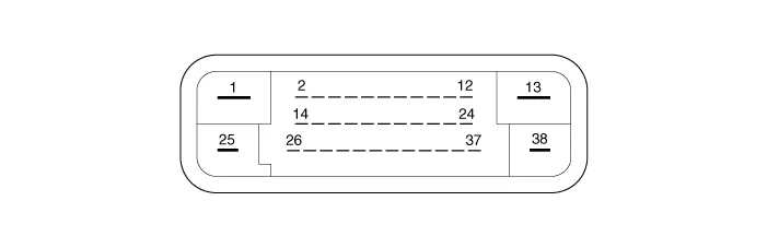
|
Pin No
|
Description
|
Current (AMPS)
|
Resistance (mΩ)
|
Remark
|
| 1 | POS. BATTERY 2. (MOTOR) | 40A | 10 | |
| 2 | - | |||
| 3 | - | |||
| 4 | - | |||
| 5 | - | |||
| 6 | - | |||
| 7 | P-CAN Low | 100 mA | 250 | |
| 8 | P-CAN High | 100 mA | 250 | |
| 9 | SENSOR REAR LEFT POWER | 150 mA | 250 | |
| 10 | SENSOR REAR RIGHT POWER | 150 mA | 250 | |
| 11 | SENSOR FRONT RIGHT POWER | 150 mA | 250 | |
| 12 | SENSOR FRONT LEFT POWER | 150 mA | 250 | |
| 13 | PUMP MOTOR GROUND | 40A | 10 | |
| 14 | - | |||
| 15 | - | |||
| 16 | - | |||
| 17 | - | |||
| 18 | - | |||
| 19 | - | |||
| 20 | - | |||
| 21 | SENSOR REAR LEFT GROUND | 40 mA | 250 | |
| 22 | SENSOR REAR RIGHT GROUND | 40 mA | 250 | |
| 23 | SENSOR FRONT RIGHT GROUND | 40 mA | 250 | |
| 24 | SENSOR FRONT LEFT GROUND | 40 mA | 250 | |
| 25 | BATTERY (+) : SOLENOID | 30A | 10 | |
| 26 | - | |||
| 27 | - | |||
| 28 | - | |||
| 29 | - | |||
| 30 | BRAKE LIGHT SWITCH | 1.2 mA | 250 | |
| 31 | - | |||
| 32 | IGN | 10 mA | 50 | |
| 33 | - | |||
| 34 | ESS DRIVE SIGNAL | 1.2 mA | 250 | |
| 35 | - | |||
| 36 | - | |||
| 37 | SENSOR FRONT RIGHT OUTPUT | 50 mA | 250 | |
| 38 | GROUND | 30A | 10 |
Standard Flow of Diagnostic TroubleshootingNotes With Regard To DiagnosisThe phenomena listed in the following table are not abnormal. Condition Explanation System check soundWhen starting the engine, a thudding sound can sometimes be heard coming from inside the engine compartment.
Components and components location Components[LHD]1. Front - right (FR)2. Rear - left (RL)3. Rear - right (RR)4. Front - left (FL)5. MC26. MC17. ABS control module (HECU)8.
Other information:
Hyundai Elantra (CN7) 2021-2026 Service Manual: Immobilizer Control Unit
Components and components location Components (1)With Smart KeyConnector Pin Information Pin no Connector A Connector B Connector C Connector D Connector E 1ESCL
Hyundai Elantra (CN7) 2021-2026 Service Manual: Description and operation
DescriptionThe cruise control system is engaged by the cruise "ON/OFF" main switch located on right of steering wheel column. The system has the capability to cruise, coast, accelerate and resume speed.It also has a safety interrupt, engaged upon depressing brake or shifting select lever.
Categories
- Manuals Home
- Hyundai Elantra Owners Manual
- Hyundai Elantra Service Manual
- Integrated Thermal Management Module (ITM)
- Brake bleeding procedures
- Body Electrical System
- New on site
- Most important about car
