Hyundai Elantra (CN7): Vehicle Information / Exterior Overview

Front view
1. Hood
2. Headlamp
3. Tires and wheels
4. Side view mirror
5. Sunroof
6. Front windshield wiper blades
7. Windows
8. Front radar
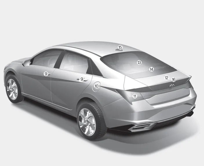
Rear view
9. Door handle
10. Fuel filler door
11. Rear combination lamp
12. Trunk
13. Defroster / Glass antenna
14. High mounted stop lamp
15. Antenna
16. Rear view camera
1. Inside door handle 2. Side view mirror control switch 3. Central door lock switch 4. Power window switches 5. Power window lock button 6. Steering wheel tilt/telescopic lever 7.
Other information:
Hyundai Elantra (CN7) 2021-2026 Service Manual: Refrigerant Line
Components and components location Components Location1. Refrigerant Pipe Assembly Repair procedures Replacement1.If the compressor is marginally operable, run the engine at idle speed, and let the air conditioning work for a few minutes, then shut the engine off.
Hyundai Elantra (CN7) 2021-2026 Service Manual: Blower Unit
Components and components location Component Location1. Blower unit assemblyComponents1. Blower unit assebmly2. Blower upper cover [LH]3. Duct seal4. Blower upper cover [RH]5. Intake actuator6. Air filter cover7. Intake door8. Air filter9. Blower upper case10.
Categories
- Manuals Home
- Hyundai Elantra Owners Manual
- Hyundai Elantra Service Manual
- Auto Hold. Warning messages
- Engine Control / Fuel System
- Troubleshooting
- New on site
- Most important about car
