
Hyundai Elantra (CN7): Front Door / Front Door Latch
Components and components location
| Component Location |
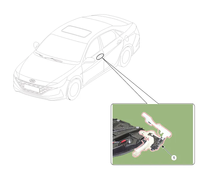
| 1. Front door latch |
Repair procedures
| Replacement |
| 1. | Remove the front door module. (Refer to Front Door - "Front Door Module") |
| 2. | Remove the front door inside handle cage (A) by pulling it in the direction of the arrow.
|

| 3. | Separate the front door outside handle base connector (A).
|

| 4. | Separate the front door outside handle connector wiring harness (A).
|

| 5. | Remove the front door latch assembly (A) by pulling it in the direction of the arrow.
|

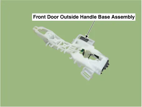
| 6. | Remove the front door outside handle base (A) by pushing in the lock pins located in the back.
|

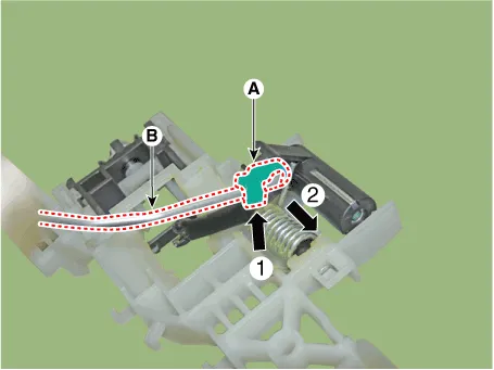
| 7. | Slide the locking pin (A) in the direction of the arrow to release the lock and then remove the rod (B).
|
| 8. | To install, reverse the removal procedure.
|

Repair procedures Replacement[Front door side weatherstrip]1.Loosen the front door checker (B) mounting bolt. Tightening torque : 18.
Other information:
Hyundai Elantra (CN7) 2021-2026 Service Manual: Ignition Switch Assembly. Repair procedures
Repair procedures Replacement1.Disconnect the negative (-) battery terminal.2.Remove the crash pad lower panel.(Refer to Body - "Crash Pad")3.Remove the steering column upper & Lower shroud.4.Remove the ignition switch and disconnecting the Key Warning / immobilizer connector.
Hyundai Elantra (CN7) 2021-2026 Service Manual: General safety information and caution
Instructions (R-134a)When Handling Refrigerant1.R-134a liquid refrigerant is highly volatile. A drop on the skin of your hand could result in localized frostbite. When handling the refrigerant, be sure to wear gloves. 2.It is standard practice to wear goggles or glasses to protect your eyes, and gloves to protect your hands.
Categories
- Manuals Home
- Hyundai Elantra Owners Manual
- Hyundai Elantra Service Manual
- Specifications
- Front Radar Unit
- Fuse/Relay Panel Description. Engine compartment fuse panel
- New on site
- Most important about car
