Hyundai Elantra (CN7): AVN System / Front monitor
Hyundai Elantra (CN7) 2021-2026 Service Manual / Body Electrical System / AVN System / Front monitor
Components and components location
| Components |
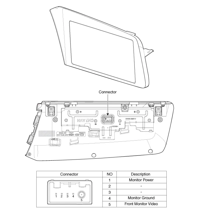
Repair procedures
| Removal |
10.25" Cluster + 10.25" Monitor
|

| 1. | Disconnect the negative (-) battery terminal. |
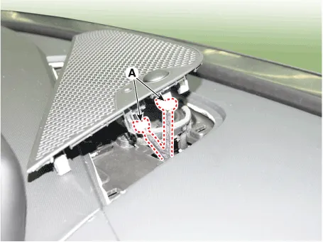
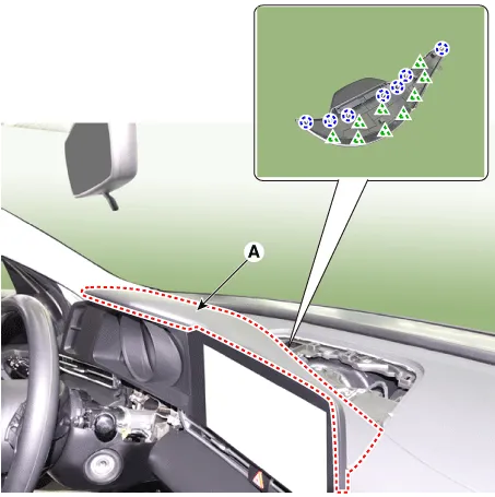
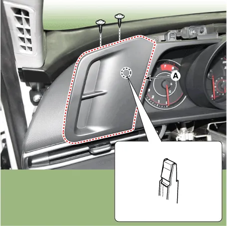
| 2. | Using a flat-tip screwdriver or remover, remove the photo sensor cover (A).
|

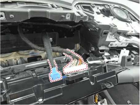
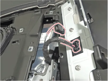
| 3. | Disconnect photo sensor connector and security sensor connector (A).
|
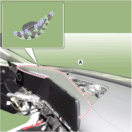
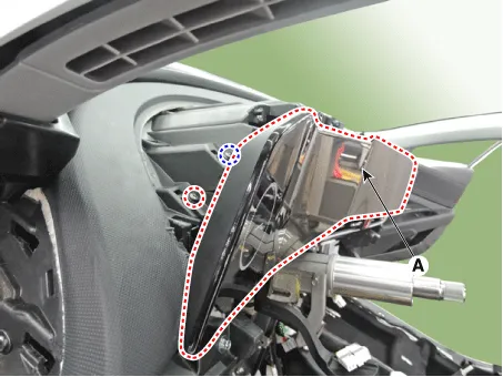
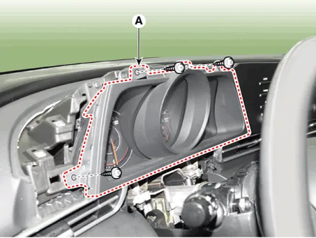
| 4. | Using a flat-tip screwdriver or remover, remove the cluster fascia upper garnish (A).
|
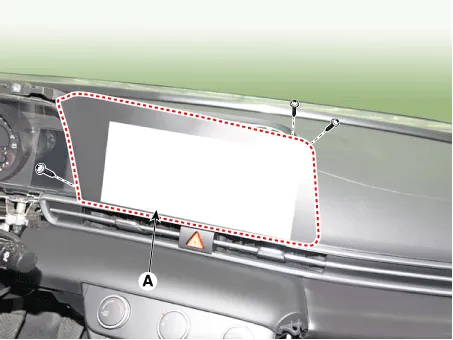
| 5. | Remove the AVN monitor (A) after loosening mounting screws.
|

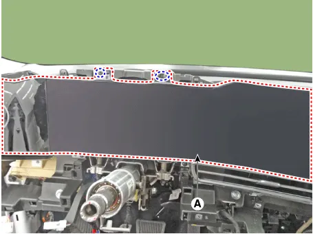
| 6. | Remove the AVN monitor after disconnecting cluster connectors and monitor connectors.
|
4.25" Cluster + 10.25" Monitor
| 1. | Disconnect the negative (-) battery terminal. |
| 2. | Using a flat-tip screwdriver or remover, remove the photo sensor cover (A).
|
| 3. | Disconnect photo sensor connector and security sensor connector (A).
|
| 4. | Using a flat-tip screwdriver or remover, remove the cluster fascia upper garnish (A).
|
| 5. | Remove the cluster fascia side panel (A).
|
| 6. | Remove the cluster fascia panel (A) after loosening mounting screws.
|
| 7. | Remove the AVN monitor (A) after loosening mounting screws.
|
| 8. | Remove the AVN monitor after disconnecting monitor connectors.
|
| Installation |
10.25" Cluster + 10.25" Monitor
| 1. | Install the AVN monitor after connecting cluster connectors and monitor connectors. |
| 2. | Install the cluster fascia upper garnish. |
| 3. | Install photo sensor cover. |
| 4. | Connect the negative (-) battery terminal.
|
4.25" Cluster + 10.25" Monitor
| 1. | Install the AVN monitor after connecting cluster connectors and monitor connectors. |
| 2. | Install the cluster fascia panel. |
| 3. | Install the cluster fascia side panel. |
| 4. | Install the cluster fascia upper garnish. |
| 5. | Install photo sensor cover. |
| 6. | Connect the negative (-) battery terminal.
|
Repair procedures Inspection1.Disconnector the negative (-) battery terminal.2.Remove the overhead console lamp.(Refer to Body Electrical System - "Overhead Console Lamp")3.
Other information:
Hyundai Elantra (CN7) 2021-2026 Service Manual: Ignition Switch Assembly. Repair procedures
Repair procedures Replacement1.Disconnect the negative (-) battery terminal.2.Remove the crash pad lower panel.(Refer to Body - "Crash Pad")3.Remove the steering column upper & Lower shroud.4.Remove the ignition switch and disconnecting the Key Warning / immobilizer connector.
Hyundai Elantra (CN7) 2021-2026 Service Manual: Refrigerant Line
Components and components location Components Location1. Refrigerant Pipe Assembly Repair procedures Replacement1.If the compressor is marginally operable, run the engine at idle speed, and let the air conditioning work for a few minutes, then shut the engine off.
Categories
- Manuals Home
- Hyundai Elantra Owners Manual
- Hyundai Elantra Service Manual
- Integrated Thermal Management Module (ITM)
- Brake System
- Instrument Panel Overview
- New on site
- Most important about car

Copyright © 2026 www.helantra7.com - 0.0291