Hyundai Elantra (CN7): Body (Interior and Exterior) / Fuel Filler Door
Hyundai Elantra (CN7) 2021-2026 Service Manual / Body (Interior and Exterior) / Fuel Filler Door
Components and components location
| Component Location |
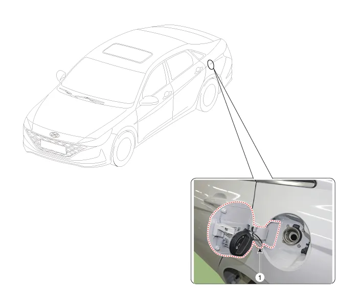
| 1. Fuel filler door |
Repair procedures
| Replacement |
[Fuel filler door]
|

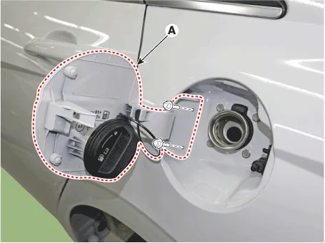
| 1. | Open the fuel filler door (A).
|

| 2. | Loosen the mounting bolts and remove the fuel filler door (A).
|
| 3. | To install, reverse the removal procedure.
|

| [Fuel filler door cable] |
|

| 1. | Remove the front seat assembly. (Refer to Front Seat - "Front Seat Assembly") |
| 2. | Remove the rear seat assembly. (Refer to rear Seat - "Rear Seat Assembly") |
| 3. | Remove the floor console assembly. (Refer to Floor Console - "Floor Console Assembly") |
| 4. | Remove the center pillar lower trim. (Refer to Interior Trim - "Center Pillar Trim") |
| 5. | Remove the cowl side trim. (Refer to Interior Trim - "Cowl Side Trim") |
| 6. | Remove the luggage side trim. (Refer to Interior Trim - "Cowl Side Trim") |
| 7. | Remove the floor carpet. (Refer to "Floor carpet") |
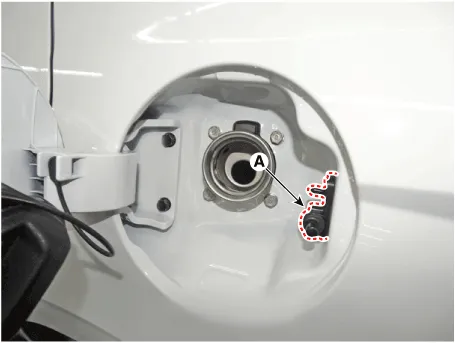
| 8. | Loosen the mounting bolt and remove the fuel filler door catch (A).
|
| 9. | Disconnect the fuel filler door barcket (A), remove the cable (B).
|

| 10. | To install, reverse the removal procedure.
|
| [Fuel filler door catch] |
| 1. | Remove the front seat assembly [LH]. (Refer to Front Seat - "Front Seat Assembly") |
| 2. | Remove the front door scuff trim [LH]. (Refer to Interior Trim - "Front Door Scuff Trim") |
| 3. | Remove the cowl side trim [LH]. (Refer to Interior Trim - "Cowl Side Trim") |
| 4. | Remove the floor console assembly. (Refer to Floor Console - "Floor Console Assembly") |
| 5. | Separate the floor carpet to obtain space for removing the rear heating duct. |
| 6. | Loosen the fuel filler door catch mounting bolt (A).
|
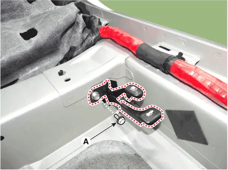
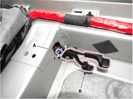
| 7. | Detach the cable (A) and remove the fuel filler door catch (B).
|
| 8. | To install, reverse the removal procedure.
|
Repair procedures Replacement • Do not apply sealant to the body. 1.Remove the trunk lid weatherstrip (A).
Other information:
Hyundai Elantra (CN7) 2021-2026 Service Manual: Intake Actuator
Description and operation DescriptionThe intake actuator is located at the blower unit. It regulates the intake door by a signal from the control unit. Pressing the intake selection switch will shift between recirculation and fresh air modes. Components and components location Components Location1.
Hyundai Elantra (CN7) 2021-2026 Service Manual: Components and components location
C
Categories
- Manuals Home
- Hyundai Elantra Owners Manual
- Hyundai Elantra Service Manual
- Suspension System
- Front Radar Unit
- General Tightening Torque Table. General information
- New on site
- Most important about car

Copyright © 2026 www.helantra7.com - 0.0196