
Hyundai Elantra (CN7): Fuel Delivery System / Fuel Pressure Regulator
Repair procedures
| Removal |
| 1. | Remove the fuel pump. (Refer to Fuel Delivery System - "Fuel Pump") |
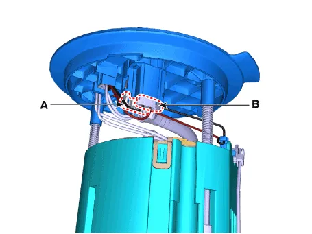
| 2. | Disconnect the fuel pump motor connector (A) and fuel sender connector (B).
|
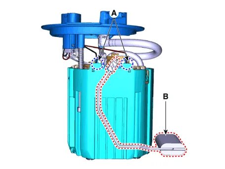
| 3. | Release the fixing hook (A) and then remove the fuel sender (B).
|
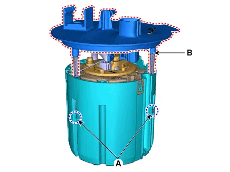
| 4. | Remove the fixing clip (A) and then disconnect the fuel feed tube (B).
|

| 5. | Remove the fixing clip (A) and then remove the head assembly (B).
|
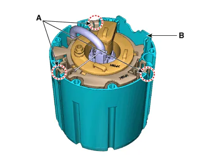
| 6. | Release the fixing hook (A) and then remove the reservoir-cup (B).
|
| 7. | Disconnect the fuel pump motor connector (A). |
| 8. | Disconnect the ground cable (B).
|
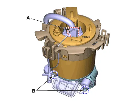
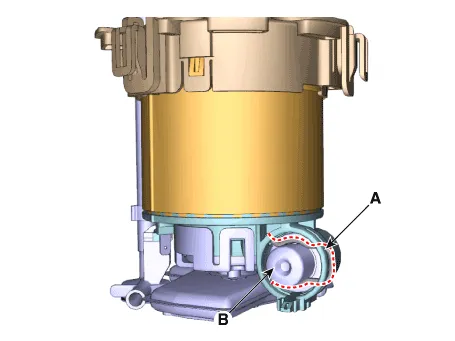
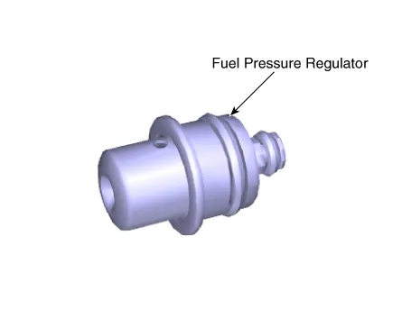
| 9. | Remove the fixing clip (A) and then disconnect the fuel pressure regulator (B).
|
| Installation |
| 1. | Install in the reverse order of removal. |
Repair procedures Removal1.Remove the fuel pump. (Refer to Fuel Delivery System - "Fuel Pump")2.Disconnect the fuel pump motor connector (A) and fuel sender connector (B).
Repair procedures Removal[Low Fuel Line]1.Release the residual pressure in fuel line. (Refer to Fuel Delivery System - "Release Residual Pressure in Fuel Line")2.
Other information:
Hyundai Elantra (CN7) 2021-2026 Service Manual: Condenser
Components and components location Components Location[General type]1. Condenser[N Line]1. Condenser Repair procedures Inspection1.Check the condenser fins for clogging and damage. If clogged, clean them with water, and blow them with compressed air.
Hyundai Elantra (CN7) 2021-2026 Service Manual: In-car Sensor
Description and operation DescriptionThe In-car air temperature sensor is built in the heater & A/C control unit.The sensor contains a thermistor which measures the temperature of the inside. The signal decided by the resistance value which changes in accordance with perceived inside temperature, is delivered to heater control unit and accor
Categories
- Manuals Home
- Hyundai Elantra Owners Manual
- Hyundai Elantra Service Manual
- Front Bumper
- Drive Mode
- Body (Interior and Exterior)
- New on site
- Most important about car
