Hyundai Elantra (CN7): Fuel Delivery System / Fuel Sender Assembly
Hyundai Elantra (CN7) 2021-2026 Service Manual / Engine Control / Fuel System / Fuel Delivery System / Fuel Sender Assembly
Repair procedures
| Removal |
| 1. | Remove the fuel pump. (Refer to Fuel Delivery System - "Fuel Pump") |
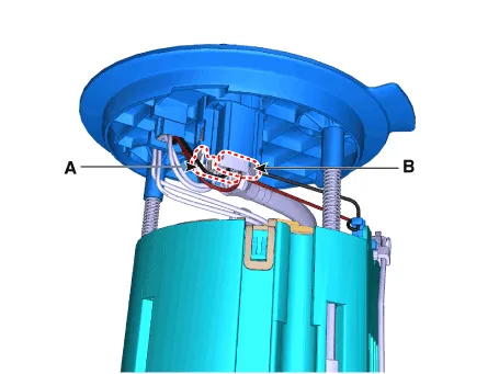
| 2. | Disconnect the fuel pump motor connector (A) and fuel sender connector (B).
|
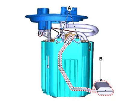
| 3. | Release the fixing hook (A) and then remove the fuel sender (B).
|
| Installation |
| 1. | Install in the reverse order of removal. |
Repair procedures Removal1.Remove the fuel pump. (Refer to Fuel Delivery System - "Fuel Pump")2.Disconnect the fuel pump motor connector (A) and fuel sender connector (B).
Repair procedures Removal1.Remove the fuel pump. (Refer to Fuel Delivery System - "Fuel Pump")2.Disconnect the fuel pump motor connector (A) and fuel sender connector (B).
Categories
- Manuals Home
- Hyundai Elantra Owners Manual
- Hyundai Elantra Service Manual
- Suspension System
- Drive Mode
- Maintenance
- New on site
- Most important about car

Copyright © 2026 www.helantra7.com - 0.0159