
Hyundai Elantra (CN7): Fuel Delivery System / Fuel Pump Motor
Repair procedures
| Removal |
| 1. | Remove the fuel pump. (Refer to Fuel Delivery System - "Fuel Pump") |
| 2. | Disconnect the fuel pump motor connector (A) and fuel sender connector (B).
|
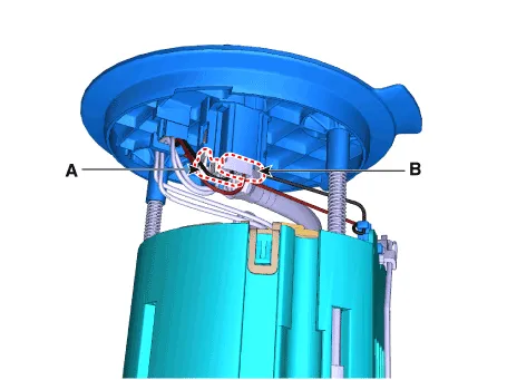
| 3. | Release the fixing hook (A) and then remove the fuel sender (B).
|

| 4. | Remove the fixing clip (A) and then disconnect the fuel feed tube (B).
|
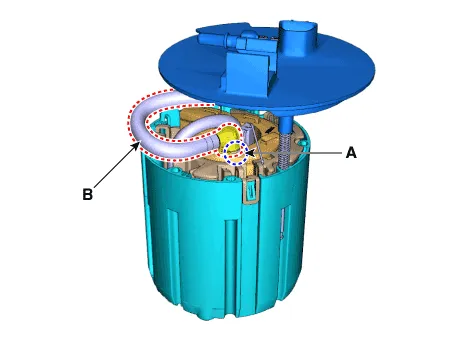
| 5. | Remove the fixing clip (A) and then remove the head assembly (B).
|
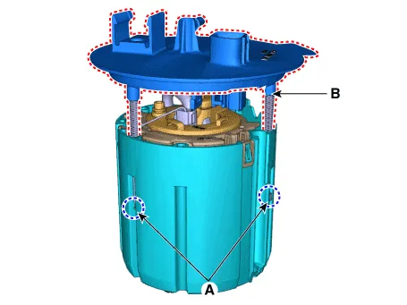
| 6. | Release the fixing hook (A) and then remove the reservoir-cup (B).
|
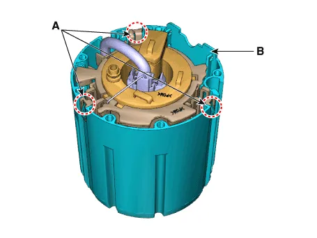
| 7. | Disconnect the fuel pump motor connector (A). |
| 8. | Disconnect the ground cable (B).
|
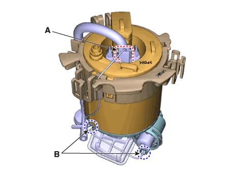
| 9. | Remove the fixing clip (A) and then disconnect the fuel pressure regulator (B).
|

| 10. | Release the fixing hook and then remove the free filter (A).
|
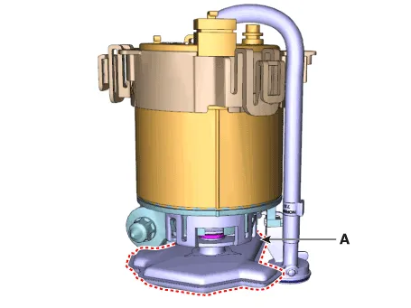
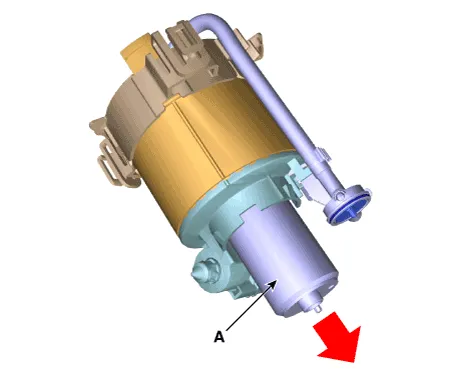
| 11. | Remove the fuel pump motor (A) from the fuel filter.
|

| Installation |
| 1. | Install in the reverse order of removal. |
Repair procedures Removal1.Remove the fuel pump. (Refer to Fuel Delivery System - "Fuel Pump")2.Disconnect the fuel pump motor connector (A) and fuel sender connector (B).
Repair procedures Removal1.Remove the fuel pump. (Refer to Fuel Delivery System - "Fuel Pump")2.Disconnect the fuel pump motor connector (A) and fuel sender connector (B).
Other information:
Hyundai Elantra (CN7) 2021-2026 Service Manual: Ignition Switch Assembly. Repair procedures
Repair procedures Replacement1.Disconnect the negative (-) battery terminal.2.Remove the crash pad lower panel.(Refer to Body - "Crash Pad")3.Remove the steering column upper & Lower shroud.4.Remove the ignition switch and disconnecting the Key Warning / immobilizer connector.
Hyundai Elantra (CN7) 2021-2026 Service Manual: ADAS Parking ECU (ADAS_PRK)
Components and components location Components and Components Location Repair procedures Removal • Use a plastic panel removal tool to remove interior trim pieces without marring the surface.• Take care not to bend or scratch the trim and panels.
Categories
- Manuals Home
- Hyundai Elantra Owners Manual
- Hyundai Elantra Service Manual
- Driver assistance system
- Body Electrical System
- Troubleshooting
- New on site
- Most important about car
