Hyundai Elantra (CN7): Fuel Delivery System / Fuel Filter
Repair procedures
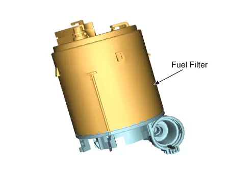
| Removal |
| 1. | Remove the fuel pump. (Refer to Fuel Delivery System - "Fuel Pump") |
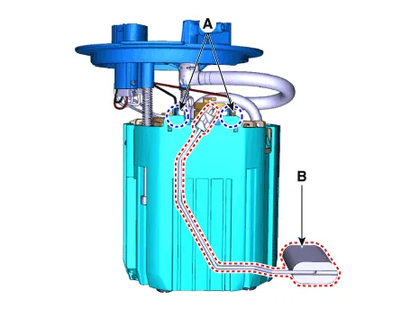
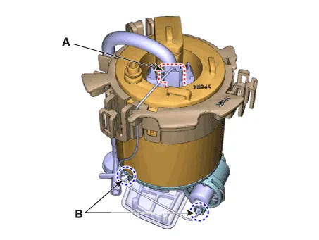
| 2. | Disconnect the fuel pump motor connector (A) and fuel sender connector (B).
|

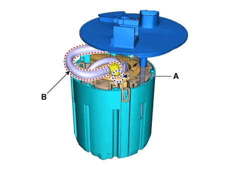
| 3. | Release the fixing hook (A) and then remove the fuel sender (B).
|
| 4. | Remove the fixing clip (A) and then disconnect the fuel feed tube (B).
|
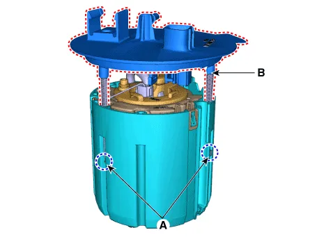
| 5. | Remove the fixing clip (A) and then remove the head assembly (B).
|
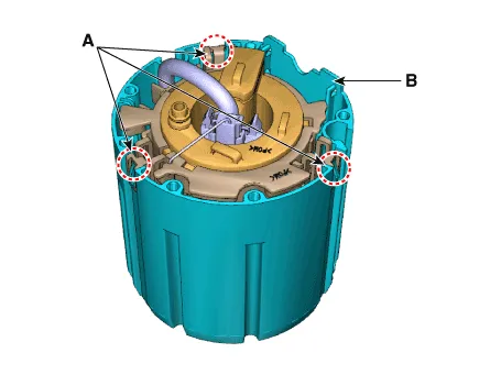
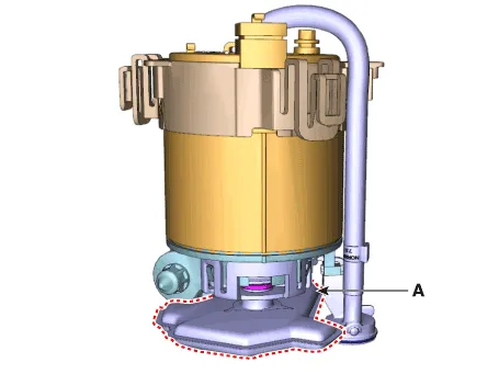
| 6. | Release the fixing hook (A) and then remove the reservoir-cup (B).
|
| 7. | Disconnect the fuel pump motor connector (A). |
| 8. | Disconnect the ground cable (B).
|
| 9. | Remove the fixing clip (A) and then disconnect the fuel pressure regulator (B).
|

| 10. | Release the fixing hook and then remove the free filter (A).
|
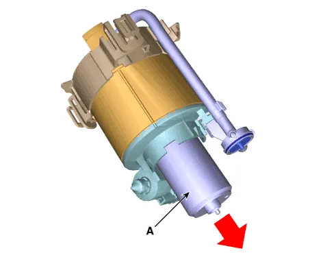
| 11. | Remove the fuel pump motor (A) from the fuel filter.
|
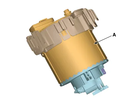
| 12. | Release the fixing hook and then remove the fuel filter (A) from the bracket.
|
| Installation |
| 1. | Install in the reverse order of removal. |
Repair procedures Inspection[Fuel Pump]1.Turn ignition switch OFF and disconnect the negative (-) battery cable.2.Remove the fuel pump assembly.3.Check motor operation by fuel pump connector (A) connecting power (No.
Repair procedures Removal1.Remove the fuel pump. (Refer to Fuel Delivery System - "Fuel Pump")2.Disconnect the fuel pump motor connector (A) and fuel sender connector (B).
Other information:
Hyundai Elantra (CN7) 2021-2026 Service Manual: Wireless Charging Lamp
Components and positions Components Repair procedures Removal • Handling wireless charging system parts by wet hands may cause electric shock. 1.Disconnect the negative (-) battery terminal.2.Remove the floor console upper cover assembly.
Hyundai Elantra (CN7) 2021-2026 Service Manual: Parking Distance Warning (PDW)
Description and operation Description• PDW consists of 8 sensors (front : 4 units, rear : 4 units) that are used to detect obstacles and transmit the result in three separate warning levels, the first, second and third to IBU via LIN communication.
Categories
- Manuals Home
- Hyundai Elantra Owners Manual
- Hyundai Elantra Service Manual
- Repair procedures
- Maintenance
- Suspension System
- New on site
- Most important about car
