Hyundai Elantra (CN7): Fuel Delivery System / Fuel Pump
Repair procedures
| Inspection |
| 1. | Turn ignition switch OFF and disconnect the negative (-) battery cable. |
| 2. | Remove the fuel pump assembly. |
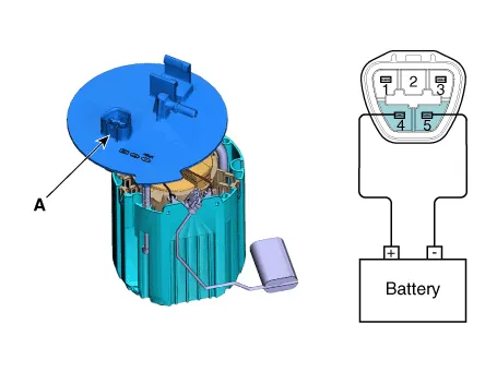
| 3. | Check motor operation by fuel pump connector (A) connecting power (No.4) and ground (No.5).
|
| 1. | Turn ignition switch OFF and disconnect the negative (-) battery cable. |
| 2. | Remove the fuel pump assembly. |
| 3. | Using an ohmmeter, measure the resistance between terminals 1 and 3 of sender connector (A) at each float level.
|
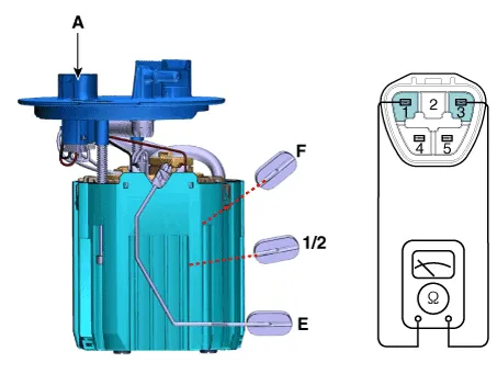
| 4. | Also check that the resistance changes smoothly when the float is moved from "E" to "F".
|
| Removal |
| 1. | Turn the ignition switch OFF and disconnect the battery (-) terminal. |
| 2. | Release the residual pressure in fuel line. (Refer to Fuel Delivery System - "Release Residual Pressure in Fuel Line") |
| 3. | Remove the rear seat. (Refer to Body (Interior and Exterior) - "Rear Seat Assembly") |
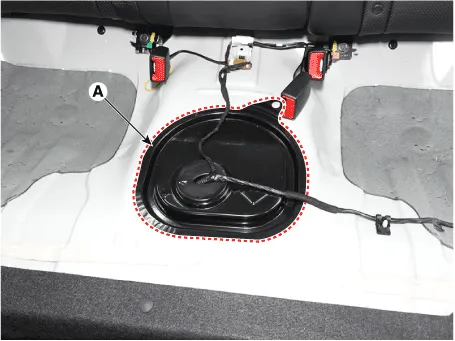
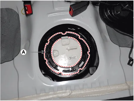
| 4. | Remove the fuel pump service cover (A).
|
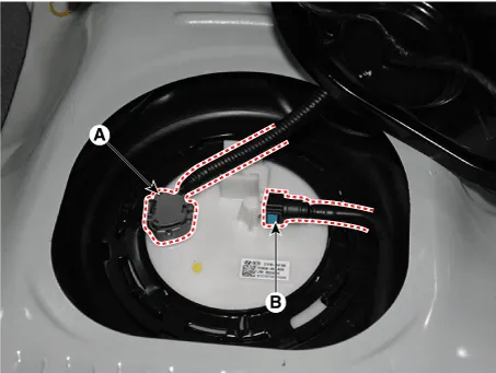
| 5. | Disconnect the fuel pump connector (A). |
| 6. | Disconnect the fuel feed tube quick-connector (B).
|
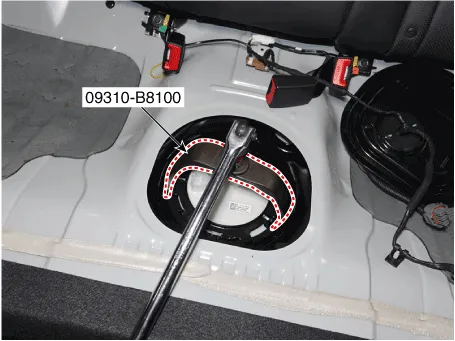
| 7. | Remove the locking ring (A) by using the special service tool [No. : 09310-B8100].
|

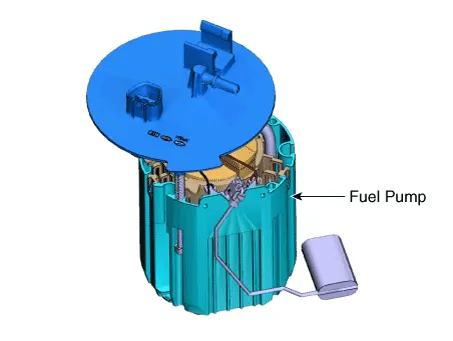
| 8. | Remove the fuel pump from the fuel tank.
|
| Installation |
| 1. | Install in the reverse order of removal.
|

Repair procedures Removal1.Release the residual pressure in fuel line.(Refer to Fuel Delivery System - "Release Residual Pressure in Fuel Line")2.Turn ignition switch OFF and disconnect the negative (-) battery cable.
Repair procedures Removal1.Remove the fuel pump. (Refer to Fuel Delivery System - "Fuel Pump")2.Disconnect the fuel pump motor connector (A) and fuel sender connector (B).
Other information:
Hyundai Elantra (CN7) 2021-2026 Service Manual: Photo Sensor
Description and operation Description 1.The photo sensor is located at the center of the defrost nozzles.2.The photo sensor contains a photovoltaic (sensitive to sunlight) diode. The solar radiation received by its light receiving portion, generates an electromotive force in proportion to the amount of radiation received which is transferred to
Hyundai Elantra (CN7) 2021-2026 Service Manual: Warning Indicator
Components and components location Components1. BSD Indicator2. Side repeater lamp Repair procedures Inspection1.Disconnect the negative (-) battery terminal.2.Remove the front door trim.(Refer to Body - "Front door trim")3.Disconnect the power door mirror connector from the harness4.
Categories
- Manuals Home
- Hyundai Elantra Owners Manual
- Hyundai Elantra Service Manual
- Integrated Thermal Management Module (ITM)
- Engine Control / Fuel System
- Brake System
- New on site
- Most important about car
