
Hyundai Elantra (CN7): Fuel Delivery System / Fuel Tank
Repair procedures
| Removal |
| 1. | Release the residual pressure in fuel line. (Refer to Fuel Delivery System - "Release Residual Pressure in Fuel Line") |
| 2. | Turn ignition switch OFF and disconnect the negative (-) battery cable. |
| 3. | Remove the rear seat. (Refer to Body - "Rear Seat Assembly") |
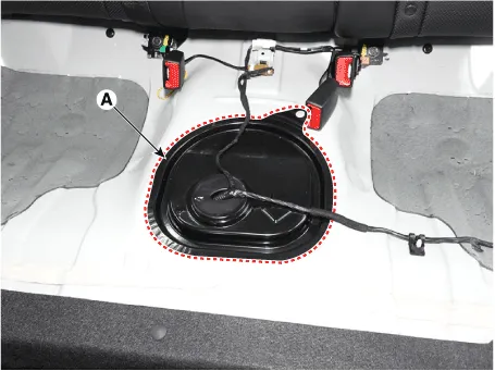
| 4. | Remove the fuel pump service cover (A).
|
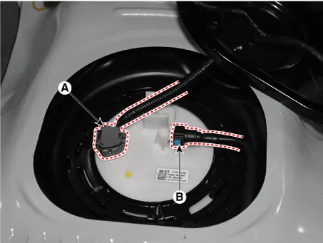
| 5. | Disconnect the fuel pump connector (A). |
| 6. | Disconnect the fuel feed tube quick-connector (B).
|
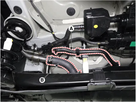
| 7. | Disconnect the leveling hose (A). |
| 8. | Disconnect the fuel filler hose (B).
|
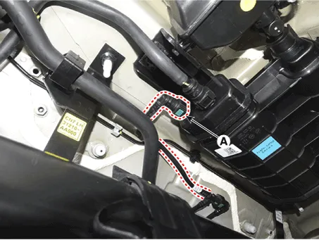
| 9. | Disconnect the vapor hose quick-connector (A)
|
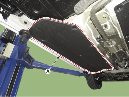
| 10. | Remove the floor under cover (A).
|
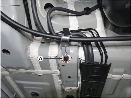
| 11. | Separate the brake line after removing the bracket mounting bolt (A).
|
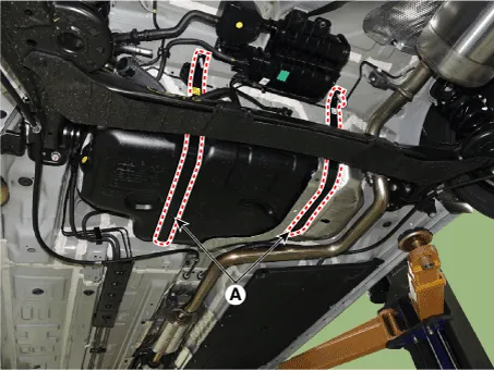
| 12. | Remove the fuel tank band (A).
|

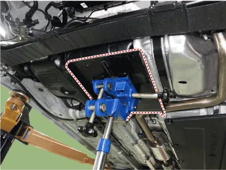
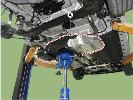
| 13. | Remove the fuel tank (A).
|
| Installation |
| 1. | Install in the reverse order of removal. |
Release Residual Pressure in Fuel Line • There may be some residual pressure even after "Release Residual Pressure in Fuel Line" work, so cover the hose connection with a shop towel to prevent residual fuel from spilling out before disconnecting any fuel connection.
Repair procedures Inspection[Fuel Pump]1.Turn ignition switch OFF and disconnect the negative (-) battery cable.2.Remove the fuel pump assembly.3.Check motor operation by fuel pump connector (A) connecting power (No.
Other information:
Hyundai Elantra (CN7) 2021-2026 Service Manual: Photo Sensor
Description and operation Description 1.The photo sensor is located at the center of the defrost nozzles.2.The photo sensor contains a photovoltaic (sensitive to sunlight) diode. The solar radiation received by its light receiving portion, generates an electromotive force in proportion to the amount of radiation received which is transferred to
Hyundai Elantra (CN7) 2021-2026 Service Manual: Rear Corner Radar Unit
Specifications Specifications Items Blind-Spot Collision Warning (BCW) Blind-Spot Collision- Avoidance Assist-Rear (BCA-R) Rated voltageDC 12VOperating voltage9V - 16VOperating speed30 km/h - 255 km/h60 km/h - 180 km/hSensible distance70m Curvature radiusStart : More
Categories
- Manuals Home
- Hyundai Elantra Owners Manual
- Hyundai Elantra Service Manual
- Maintenance
- Function settings
- Front Radar Unit
- New on site
- Most important about car
