Hyundai Elantra (CN7): Ignition System / Ignition Coil
Description and operation
| Description |
Troubleshooting
| Troubleshooting |
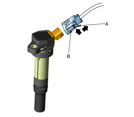
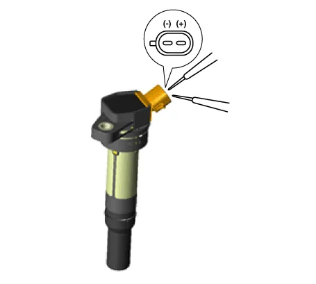
| 1. | Remove the connector (A) and reinstall it.
|
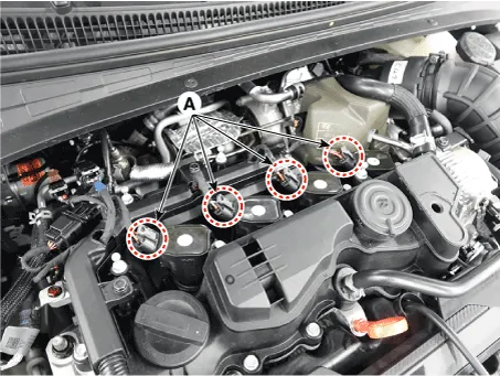
|

Specifications
| Specification |
|
Item
|
Specification
|
| Primary Coil Resistance (Ω) | 0.75 ± 15% [20°C (68°F)] |
| Secondary Coil Resistance (kΩ) | 5.9 ± 15% [20°C (68°F)] |
Schematic diagrams
| Circuit Diagram |

Repair procedures
| Removal |
| 1. | Turn ignition switch OFF and disconnect the negative (-) battery cable. |
| 2. | Remove the engine cover. |
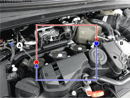
| 3. | Disconnect the ignition coil connector (A).
|
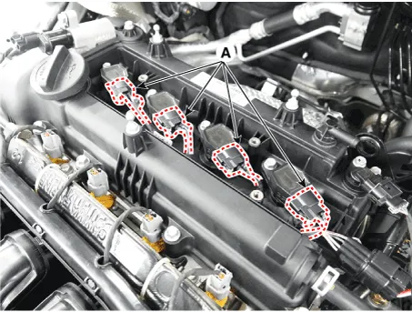
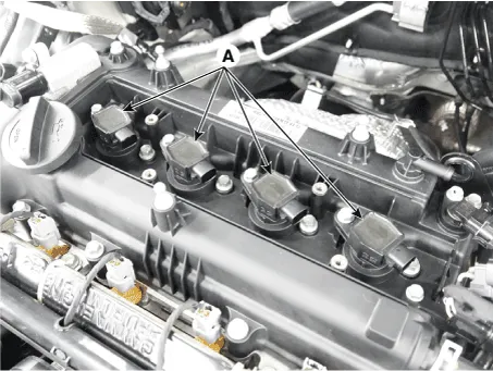
| 4. | Remove the ignition coil (A).
|
| Installation |
| 1. | Install in the reverse order of removal. |
| Inspection |
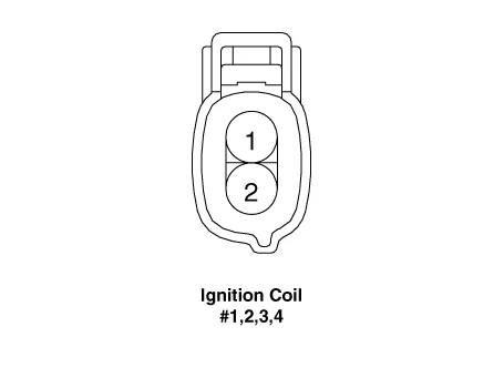
| 1. | Measure the primary coil resistance between terminals 1 and 2.
|
On-vehicle InspectionInspect ignition coil assembly and Perform spark test1.Check for DTCs. • If a DTC is present, perform troubleshooting in accordance with the procedure for that DTC.
Description and operation DescriptionA spark plug is a device for delivering electric current from an ignition system to the combustion chamber of a spark-ignition engine to ignite the compressed fuel/air mixture therein by means of an electric spark, while containing combustion pressure within the engine.
Other information:
Hyundai Elantra (CN7) 2021-2026 Service Manual: Compressor oil
Repair procedures Oil Specification1.The HFC-134a system requires synthetic (PAG) compressor oil whereas the R-12 system requires mineral compressor oil. The two oils must never be mixed.2.Compressor (PAG) oil varies according to compressor model. Be sure to use oil specified for the model of compressor.
Hyundai Elantra (CN7) 2021-2026 Service Manual: Blower Resistor (Manual)
Repair procedures Inspection1.Measure the resistance between the terminals.2.The measured resistance is not within specification, the blower resistor must be replaced. (After removing the resistor)Replacement1.Disconnect the negative (-) battery terminal.
Categories
- Manuals Home
- Hyundai Elantra Owners Manual
- Hyundai Elantra Service Manual
- Engine Control / Fuel System
- Body (Interior and Exterior)
- Integrated Thermal Management Module (ITM)
- New on site
- Most important about car
