Hyundai Elantra (CN7): Crash Pad / Main Crash Pad Assembly
Components and components location
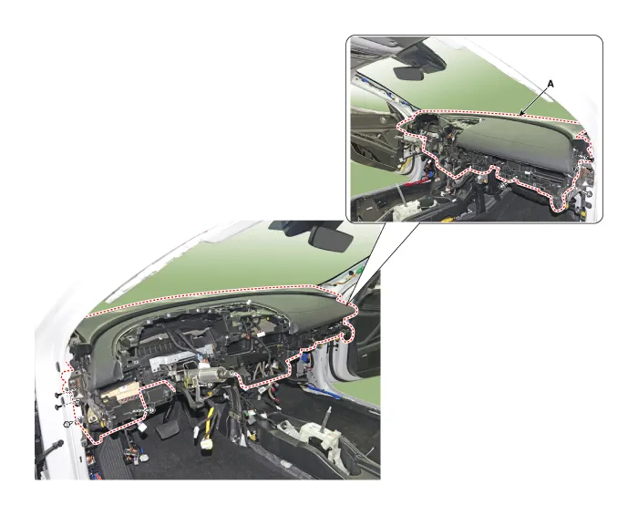
| Component Location |
| [This illustration shows the LHD type. RHD type is symmetrical.] |

| 1. Main crash pad assembly |
Repair procedures
| Replacement |
|

|

| 1. | Disconnect the negative ( - ) battery terminal. |
| 2. | Remove the floor console assembly. (Refer to Floor Console - "Floor Console Assembly") |
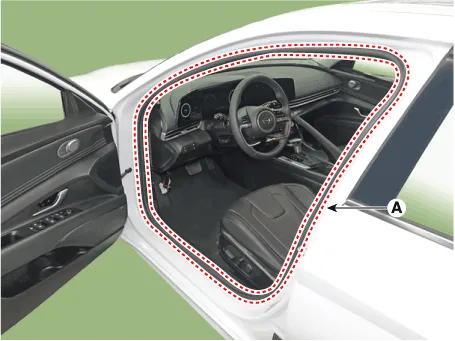
| 3. | Remove the front pillar trim.
|


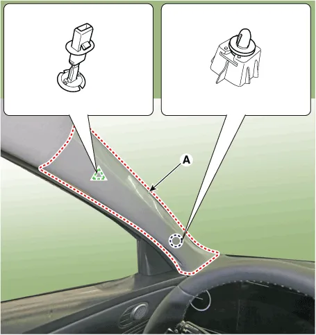

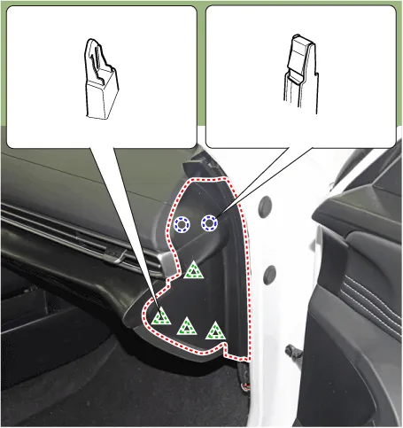
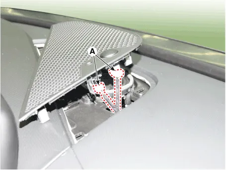
| 4. | Detach the clips, then remove the front door body side weatherstrip (A). [LH]
[RH]
|
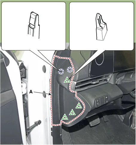
| 5. | Using a screwdriver or remover, remove the crash pad side cover (A). [LH]
[RH]
|
| 6. | Loosen the mounting screws, remove the crash pad lower panel (A).
|
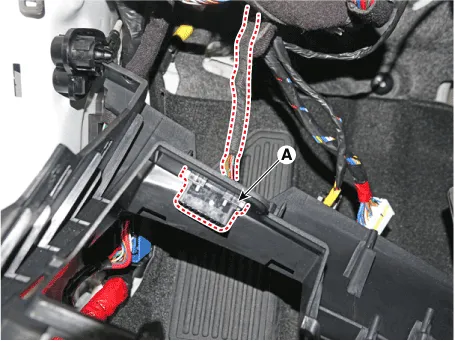
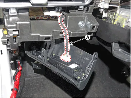
| 7. | Press the lock pin, separate diagnosis connector (A).
|
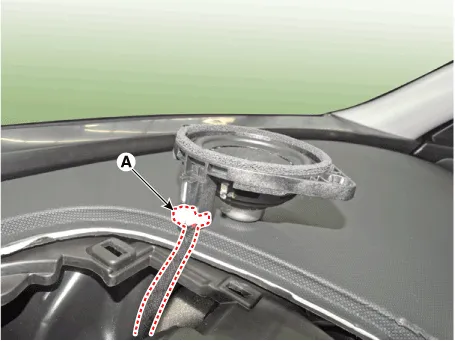
| 8. | Using a screwdriver or remover, remove the photo sensor cover (A).
|
| 9. | Press the lock pin, separate the connectors (A).
|
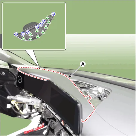
| 10. | Using a screwdriver or remover, remove the cluster fascia panel upper garnish (A).
|
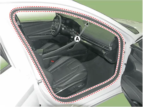
| 11. | Remove the crash pad garnish [LH]
[RH]
|
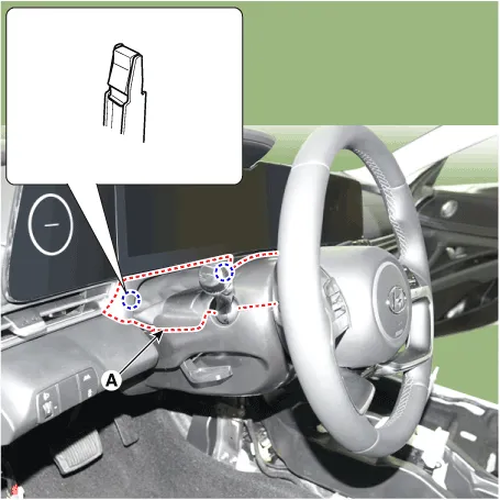
| 12. | Loosen the mounting screws by turning the steering wheel to the left and right, and remove the steering column shroud lower panel (A).
|

| 13. | Remove the instrument cluster. (Refer to Body Electrical System - "Instrument Cluster") |
| 14. | Loosen the mounting screw, remove the center speaker (A).
|

| 15. | Press the lock pin, separate the center speaker connector (A).
|
| 16. | Remove the glove box housing cover. (Refer to Crash Pad - "Glove Box Housing Cover") |
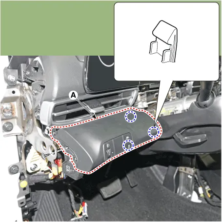
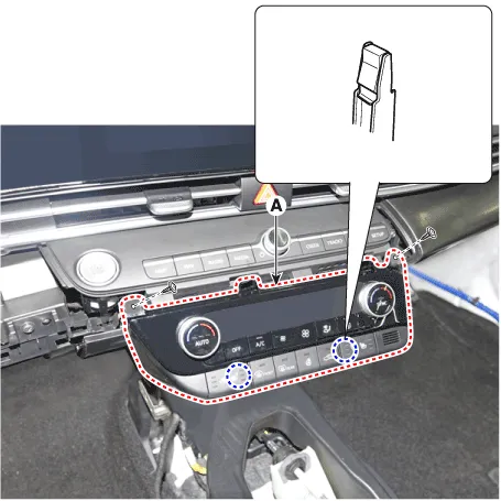
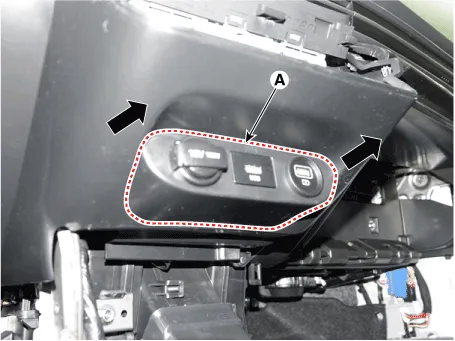
| 17. | Loosen the mounting screws, remove the A/C & heater controller unit (A).
|
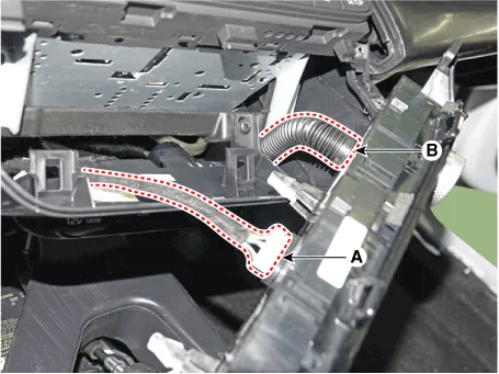
| 18. | Disconnect the A/C & heater controller connectors (A) and hose (B).
|
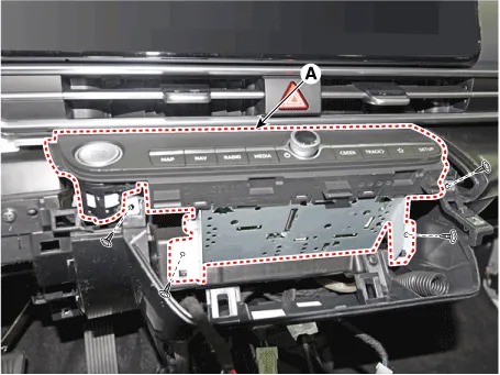
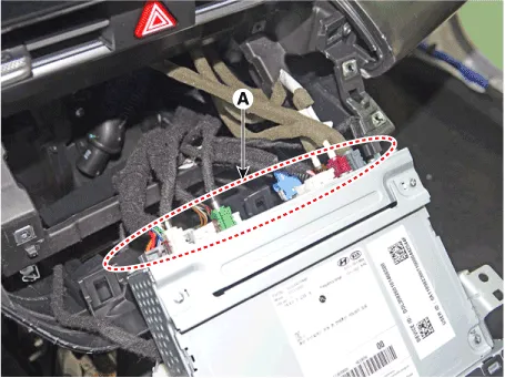
| 19. | Loosen the mounting screws, remove the AVN keyboard assembly (A).
|
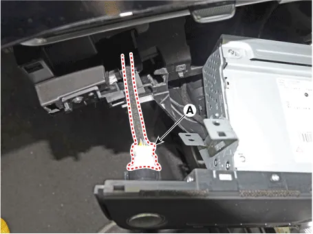
| 20. | Press the lock pin, separate the start button connector (A).
|
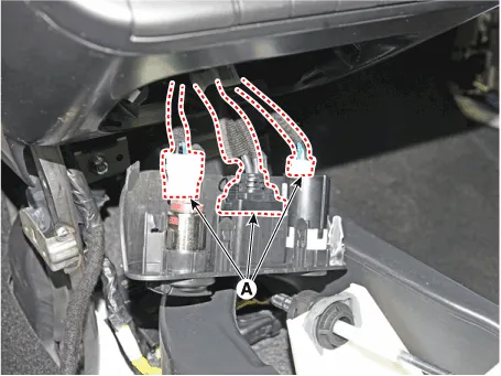
| 21. | Press the lock pin, separate the connectors (A).
|
| 22. | Remove the USB port assembly (A) by pulling it in the direction of the arrow.
|
| 23. | Press the lock pin, separate the connectors (A).
|
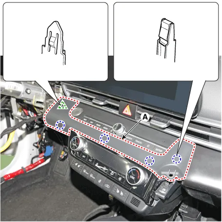
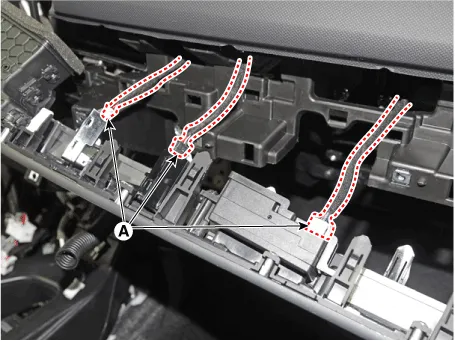
| 24. | Loosen the mounting screws, remove the crash pad center panel (A).
|
| 25. | Remove the steering wheel. (Refer to Steering System - "Steering Wheel") |
| 26. | Remove the multifunction switch assembly. (Refer to Body Electrical System - "Multifunction Switch") |
| 27. | Remove the crash pad air vent. [LH]
[RH]
|
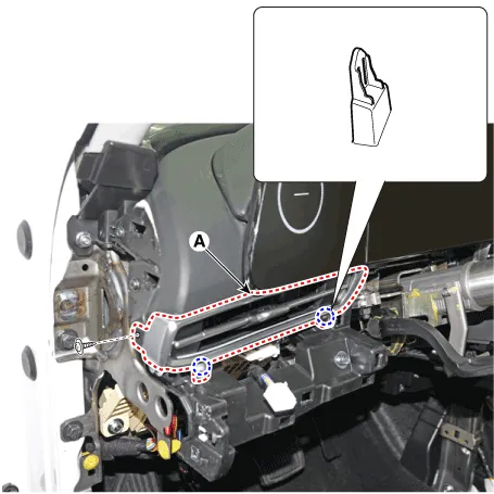

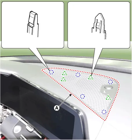
| 28. | Loosen the passenger's airbag (PAB) mounting nuts (A).
|
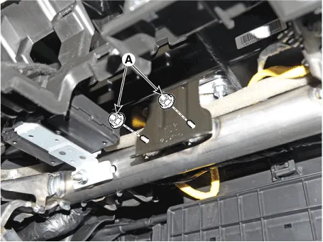
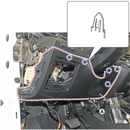
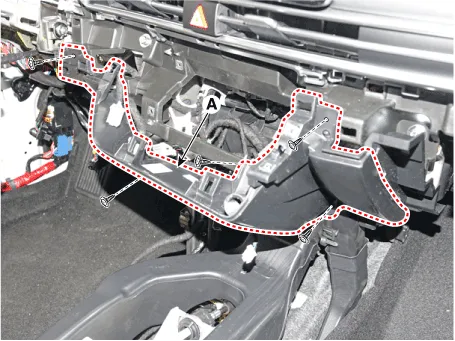
| 29. | Loosen the mounting bolts and nuts and remove the main crash pad assembly (A).
|
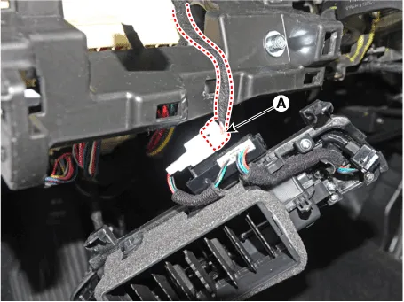
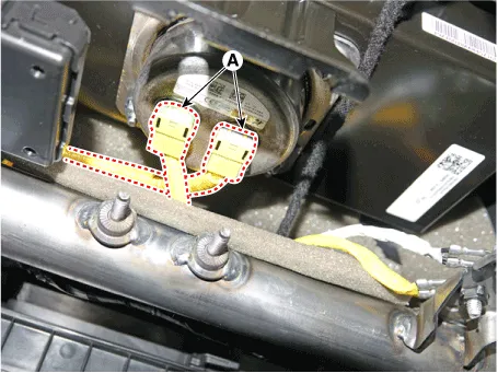
| 30. | Press the lock pin, separate the passenger's airbag (PAB) connectors (A).
|
| 31. | To install, reverse the removal procedure.
|
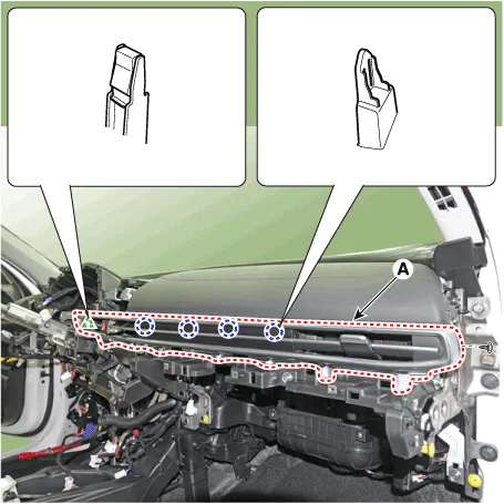
Components and components location Component Location [This illustration shows the LHD type. RHD type is symmetrical.]1. Crash pad center panel Repair procedures Replacement • When removing with a flat - tip screwdriver or remover, wrap protective tape around the tools to prevent damage to components.
Components and components location Component Location [This illustration shows the LHD type. RHD type is symmetrical.]1. Cowl cross bar assembly Repair procedures Replacement • When removing with a flat - tip screwdriver or remover, wrap protective tape around the tools to prevent damage to components.
Other information:
Hyundai Elantra (CN7) 2021-2026 Service Manual: Wireless Charging Lamp
Components and positions Components Repair procedures Removal • Handling wireless charging system parts by wet hands may cause electric shock. 1.Disconnect the negative (-) battery terminal.2.Remove the floor console upper cover assembly.
Hyundai Elantra (CN7) 2021-2026 Service Manual: Description and operation
Description and OperationBlcok Diagram • This system monitors the driving situations through the radar and the camera. Thus, for a situation out of the sensing range, the system may not normally operate. The System may be limited when : • The radar sensor or camer
Categories
- Manuals Home
- Hyundai Elantra Owners Manual
- Hyundai Elantra Service Manual
- Vehicle Information
- Engine Mechanical System
- Troubleshooting
- New on site
- Most important about car
