Hyundai Elantra (CN7): Crash Pad / Crash Pad Center Panel
Components and components location
| Component Location |
| [This illustration shows the LHD type. RHD type is symmetrical.] |
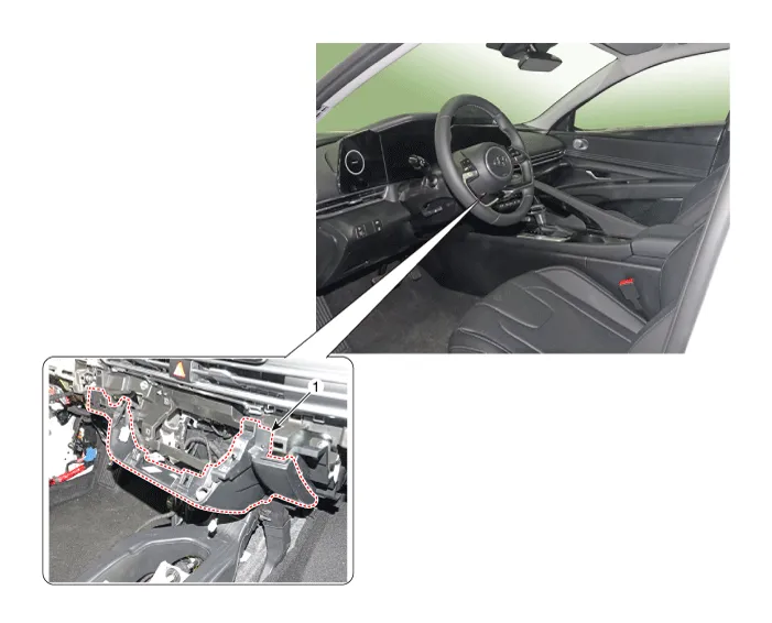
| 1. Crash pad center panel |
Repair procedures
| Replacement |
|

| 1. | Remove the crash pad garnish [CTR,RH]. (Refer to Crash Pad -"Crash Pad Garnish") |
| 2. | Remove the glove box housing cover. (Refer to Crash Pad -"Glove Box Housing Cover") |
| 3. | Remove the crash pad lower panel. (Refer to Crah Pad -"Crash Pad Lower Panel") |
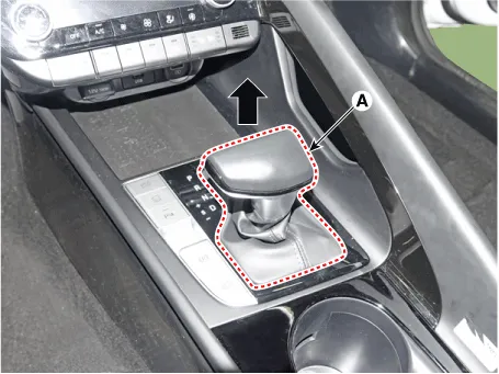
| 4. | To remove the gear knob & gear boots (A) pull both of it up.
|
| 5. | Using a screwdriver or remover, remove the floor console side garnish (A).
|

| 6. | After loosening the mounting screw and then using a screwdriver or remover, remove the console upper cover (A).
|

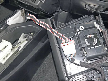
| 7. | Press the lock pin separate the console upper cover connector (A).
|
| 8. | Loosen the mounting screws, remove the A/C & heater controller unit (A).
|
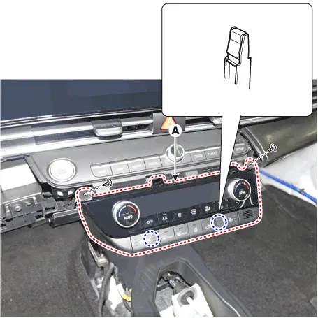
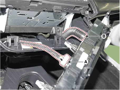
| 9. | Disconnect the A/C & heater controller connectors (A) and hose (B).
|
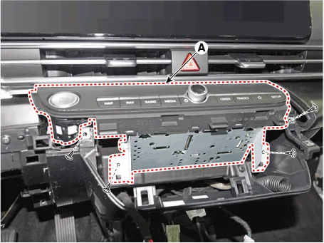
| 10. | Loosen the mounting screws, remove the AVN keyboard assembly (A).
|
| 11. | Press the lock pin, separate the start button connector (A).
|

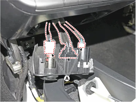
| 12. | Press the lock pin, separate the connectors (A).
|
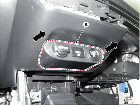
| 13. | Remove the USB port assembly (A) by pulling it in the direction of the arrow.
|
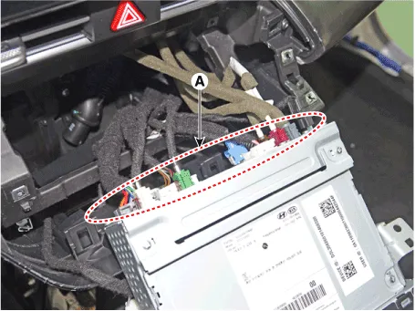
| 14. | Press the lock pin, separate the connectors (A).
|
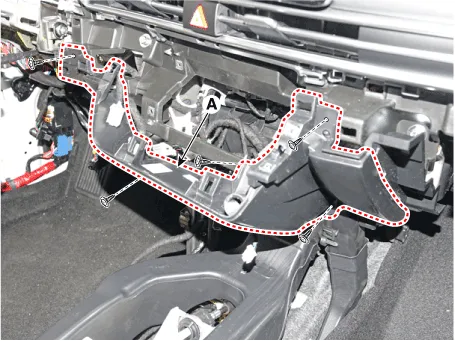
| 15. | Loosen the mounting screws, remove the crash pad center panel (A).
|
| 16. | To install, reverse the removal procedure.
|

Components and components location Component Location [This illustration shows the LHD type. RHD type is symmetrical.][LH]1. Crash pad side cover [LH][RH]1.
Components and components location Component Location [This illustration shows the LHD type. RHD type is symmetrical.]1. Main crash pad assembly Repair procedures Replacement • When removing with a flat - tip screwdriver or remover, wrap protective tape around the tools to prevent damage to components.
Other information:
Hyundai Elantra (CN7) 2021-2026 Service Manual: Repair procedures
Variant Coding When you need variant coding:– Replace Front View Camera with a new one※ EOL Variant Coding and calibration required for new replacementFront View Camera Variant CodingFront view camera variant coding makes it possible to operate functions for each vehicle type.
Hyundai Elantra (CN7) 2021-2026 Service Manual: Smart Cruise Control (SCC) Switch
Schematic diagrams Circuit DiagramTRIP / SCC / LFA Repair procedures Inspection1.Check for resistance between terminals in each switch position (LH).[LH : Audio + Hands free] Switch Resistance (±5%) SEEK Up430 ΩSEEK Down1.
Categories
- Manuals Home
- Hyundai Elantra Owners Manual
- Hyundai Elantra Service Manual
- Auto Hold. Warning messages
- Suspension System
- Brake System
- New on site
- Most important about car
