Hyundai Elantra (CN7): Lubrication System / Oil Pump
Repair procedures
| Removal and Installation |
Oil Pump
| 1. | Remove the engine room under cover. (Refer to Engine and Transaxle Assembly - "Engine Room Under Cover") |
| 2. | Drain the engine oil. (Refer to Lubrication System - "Engine Oil") |
| 3. | Remove the oil pan. (Refer to Lubrication System - "Oil Pan") |
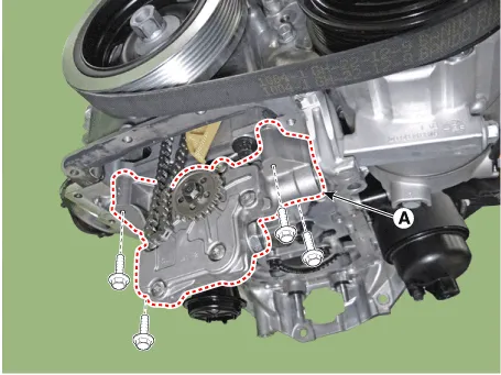
| 4. | Turn the oil pump chain tensioner (A) in the direction of the arrow and remove the oil pump chain (B) from the oil pump.
|

| 5. | Remove the oil pump (A).
|
| 6. | Install in the reverse order of removal. |
| 7. | Refill engine oil. (Refer to Lubrication System - "Engine Oil") |
| 8. | Start engine and check for oil leaks. |
Oil Pump Chain
| 1. | Disconnect the battery negative terminal. |
| 2. | Remove the timing chain. (Refer to Timing System - "Timing Chain") |
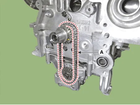
| 3. | Remove the oil pump chain tensioner (A).
|

| 4. | Remove the oil pump chain (A).
|
| 5. | Install in the reverse order of removal. |
| 6. | Refill engine oil. (Refer to Lubrication System - "Engine Oil") |
Repair procedures Removal and Installation1.Disconnect the battery negative terminal.2.Remove the engine room under cover.(Refer to Engine and Transaxle Assembly - "Engine Room Under Cover") 3.
Repair procedures Removal and Installation1.Disconnect the battery negative terminal.2.Disconnect the oil pressure control solenoid valve connector (A).
Other information:
Hyundai Elantra (CN7) 2021-2026 Service Manual: Specification
S
Hyundai Elantra (CN7) 2021-2026 Service Manual: Smart Cruise Control (SCC) Switch
Schematic diagrams Circuit DiagramTRIP / SCC / LFA Repair procedures Inspection1.Check for resistance between terminals in each switch position (LH).[LH : Audio + Hands free] Switch Resistance (±5%) SEEK Up430 ΩSEEK Down1.
Categories
- Manuals Home
- Hyundai Elantra Owners Manual
- Hyundai Elantra Service Manual
- Engine Mechanical System
- Body (Interior and Exterior)
- Troubleshooting
- New on site
- Most important about car

Copyright © 2026 www.helantra7.com - 0.0134