Hyundai Elantra (CN7): Lighting System / Overhead Console Lamp
Repair procedures
| Removal |
| 1. | Disconnect the negative (-) battery terminal. |
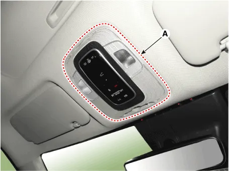
| 2. | Using a remover and remove the overhead console (A).
|
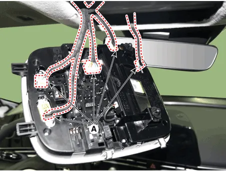
| 3. | Disconnect the overhead console connectors (A).
|
| Installation |
| 1. | Connect the overhead console connectors and install the overhead console. |
| 2. | Connect the negative (-) battery terminal. |
Repair procedures Removal[Room Lamp]1.Disconnect the negative (-) battery terminal.2.Using a screwdriver or remover, Separate the room lamp lens (A) from the room lamp.
Repair procedures Removal1.Disconnect the negative (-) battery terminal.2.Remove the crash pad airvent [RH].(Refer to Body - "Crash Pad Airvent")3.Loosen the mounting screws and remove the harzard lamp switch (A).
Other information:
Hyundai Elantra (CN7) 2021-2026 Service Manual: Description and operation
Description and OperationBlcok Diagram • This system monitors the driving situations through the radar and the camera. Thus, for a situation out of the sensing range, the system may not normally operate. The System may be limited when : • The radar sensor or camer
Hyundai Elantra (CN7) 2021-2026 Service Manual: Front View Camera Unit
Schematic diagrams Circuit Diagram Repair procedures Removal1.Disconnect the negative (-) battery terminal.2.Remove the cover (A) & (B).3.Disconnect the front view camera unit connector (A).4.Separate the fixed points (A) of coupler.5.
Categories
- Manuals Home
- Hyundai Elantra Owners Manual
- Hyundai Elantra Service Manual
- Drive Mode
- Repair procedures
- Brake System
- New on site
- Most important about car
