Hyundai Elantra (CN7): Lighting System / Room Lamp
Repair procedures
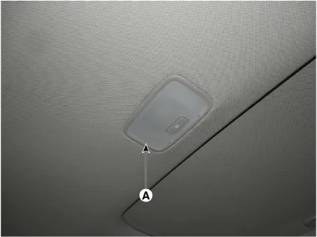
| Removal |
| 1. | Disconnect the negative (-) battery terminal. |
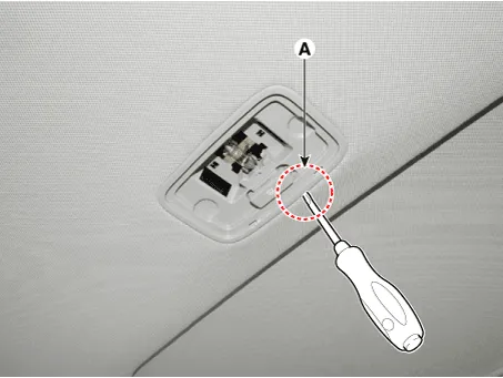
| 2. | Using a screwdriver or remover, Separate the room lamp lens (A) from the room lamp.
|

| 3. | If it is necessary to replace the bulb, remove the bulb (A) after disengaging the room lamp lens. |
| 4. | Disengage the room lamp (B) after loosening the mounting screws.
|
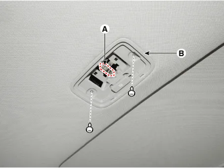

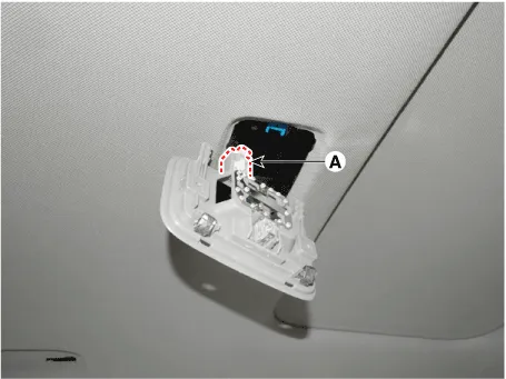
| 5. | Remove the room lamp assembly after disconnect the room lamp connector.
|
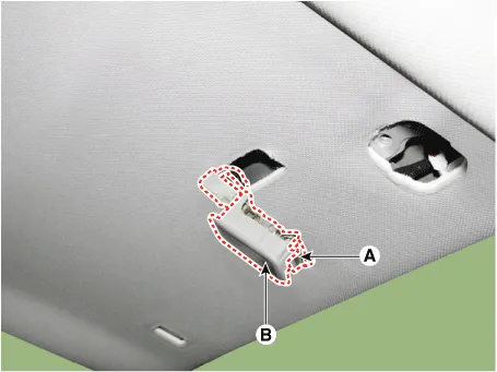
| 1. | Separate the vanity Lamp (A) from the roof trim after disengaging the mounting clip (B).
|
| Installation |
| 1. | Install the room lamp after connect the connector. |
| 2. | Install the room lamp lens |
| 3. | Connect the negative (-) battery terminal. |
| 1. | Install the vanity lamp. |
| 2. | Connect the negative (-) battery terminal. |
Repair procedures Head Lamp Aiming Instructions[Mechanical Aiming]The head lamps should be aimed with the proper beam-setting equipment, and in accordance with the equipment manufacturer's instructions.
Repair procedures Removal1.Disconnect the negative (-) battery terminal.2.Using a remover and remove the overhead console (A).3.Disconnect the overhead console connectors (A).
Other information:
Hyundai Elantra (CN7) 2021-2026 Service Manual: Wireless Power Charging Unit
Components and positions Components Circuit diagram Circuit Diagram Repair procedures Removal • Handling wireless charging system parts by wet hands may cause electric shock. 1.Disconnect the negative (-) battery terminal.
Hyundai Elantra (CN7) 2021-2026 Service Manual: Blower Unit
Components and components location Component Location1. Blower unit assemblyComponents1. Blower unit assebmly2. Blower upper cover [LH]3. Duct seal4. Blower upper cover [RH]5. Intake actuator6. Air filter cover7. Intake door8. Air filter9. Blower upper case10.
Categories
- Manuals Home
- Hyundai Elantra Owners Manual
- Hyundai Elantra Service Manual
- Brake System
- Body (Interior and Exterior)
- Maintenance
- New on site
- Most important about car
