Hyundai Elantra (CN7): Front View Camera System / Front View Camera Unit
Schematic diagrams
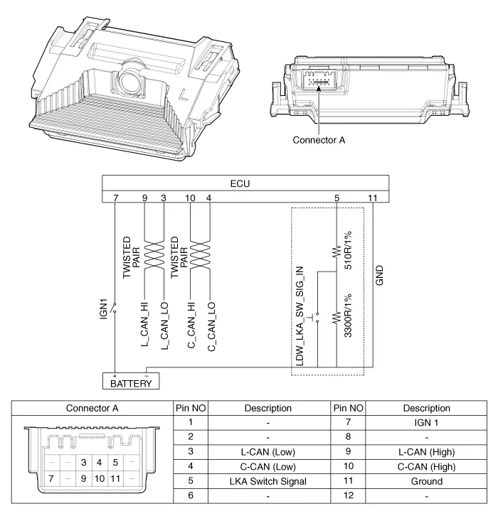
| Circuit Diagram |
Repair procedures
| Removal |
| 1. | Disconnect the negative (-) battery terminal. |
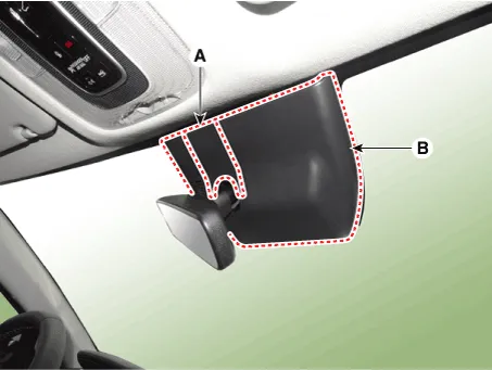
| 2. | Remove the cover (A) & (B).
|
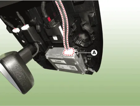
| 3. | Disconnect the front view camera unit connector (A).
|
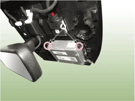
| 4. | Separate the fixed points (A) of coupler.
|
| 5. | Remove the front view camera (A).
|

| Installation |
|

| 1. | Install in the reverse order of removal. |
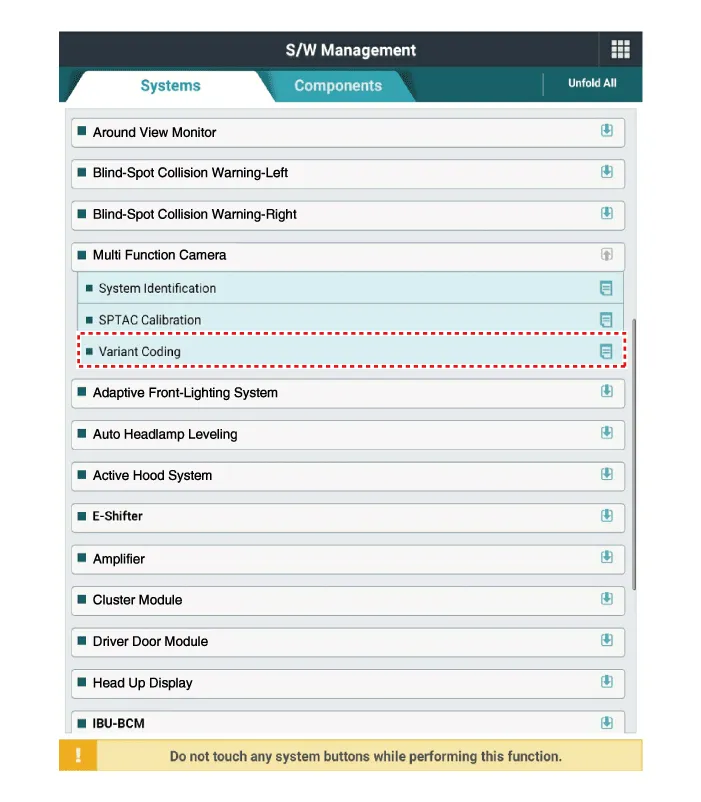
| 2. | When if replacing the front view camera with a new one, perform the "Variant Coding" procedure by using the Diagnostic Tools.
|
| 3. | Perform the front view camera unit calibration. (Refer to Repair procedures - "Service Point Target Auto Calibration (SPTAC)") |
Variant Coding When you need variant coding:– Replace Front View Camera with a new one※ EOL Variant Coding and calibration required for new replacementFront View Camera Variant CodingFront view camera variant coding makes it possible to operate functions for each vehicle type.
Other information:
Hyundai Elantra (CN7) 2021-2026 Service Manual: Auto Lighting Control System
Description and operation DescriptionIt's a system that uses illumination sensor to automatically turn ON the tail lamp and head lamp based on the change in surrounding environment's illumination condition. It activates when the vehicle enters/exits tunnel, or when the illumination condition in surrounding environment changes due to rain, snow, or
Hyundai Elantra (CN7) 2021-2026 Service Manual: Repair procedures
Inspection1.Check for resistance between terminals in each switch position (LH).[LH : Audio + Hands free] Switch Resistance (±5%) SEEK Up430 ΩSEEK Down1.11 kΩMODE2.11 kΩMUTE3.11 kΩVolume (+)4.
Categories
- Manuals Home
- Hyundai Elantra Owners Manual
- Hyundai Elantra Service Manual
- Maintenance
- Specifications
- Integrated Thermal Management Module (ITM)
- New on site
- Most important about car
