Hyundai Elantra (CN7): Body Electrical System / Power Door Locks
Components and components location
| Component Location |
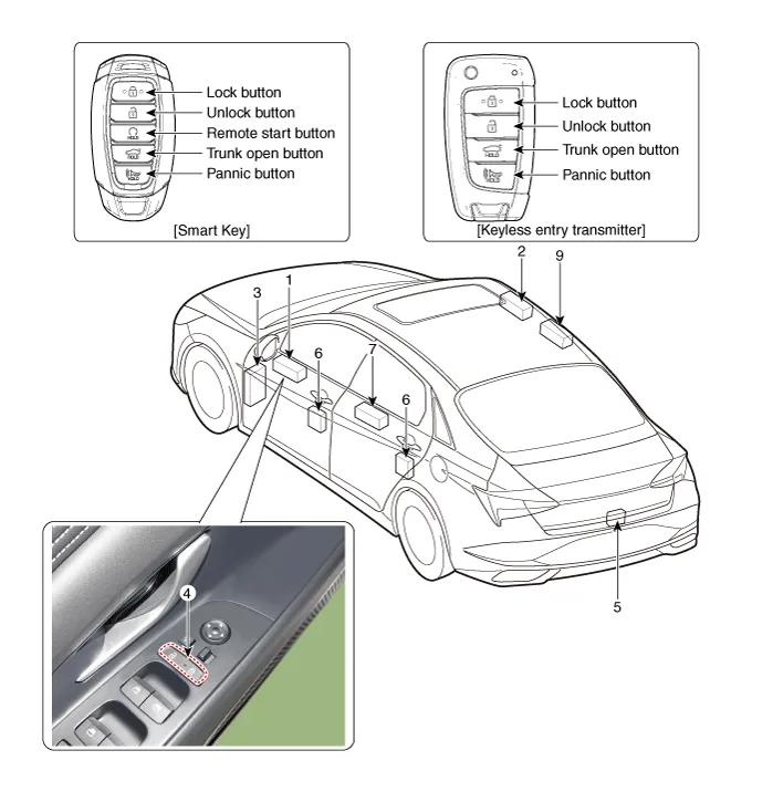
| 1. DDM (Driver Door Module) 2. ADM (Assist Door Module) 3. Integrated Central Control Unit (ICU) 4. Door lock knob 5. Trunk lid actuator | 6. Door latch module 7. Door lock/unlock switch 8. RLDM (Rear Left Door Module) 9. RRDM (Rear Right Door Module) |
Power Door Lock Module
Components and components location
| Conponents |
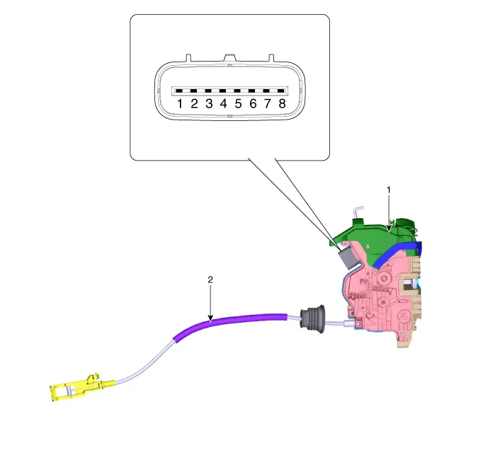
| 1. Door latch assembly | 2. Door latch cable |
Repair procedures
| Inspection |
|

| 1. | Remove the front door trim. (Refer to Body - "Front Door Trim") |
| 2. | Remove the front door module. (Refer to Body - "Front Door Module") |
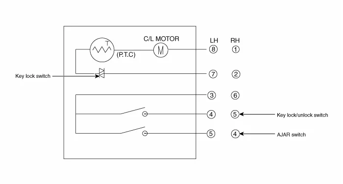
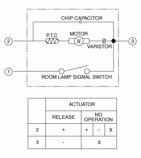
| 3. | Disconnect the connector from the actuator.
| |||||||||||||||||||||||||||||
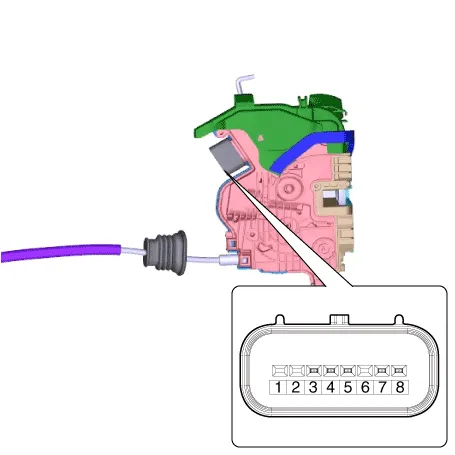
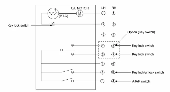
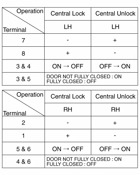
| 4. | Check actuator operation by connecting power and ground according to the table. To prevent damage to the actuator, apply battery voltage only momentarily.
|

| 1. | Remove the rear door trim. (Refer to Body - "Rear Door Trim") |
| 2. | Remove the rear door module. (Refer to Body - "Rear Door Module") |
| 3. | Disconnect the connectors from the actuator.
| |||||||||||||||||||||||||||||
| 4. | Check actuator operation by connecting power and ground according to the table. To prevent damage to the actuator, apply battery voltage only momentarily.
|
| 1. | Remove the trunk lid trim. (Refer to Body - "Trunk Lid Trim") |
| 2. | Disconnect the connector from the actuator
|
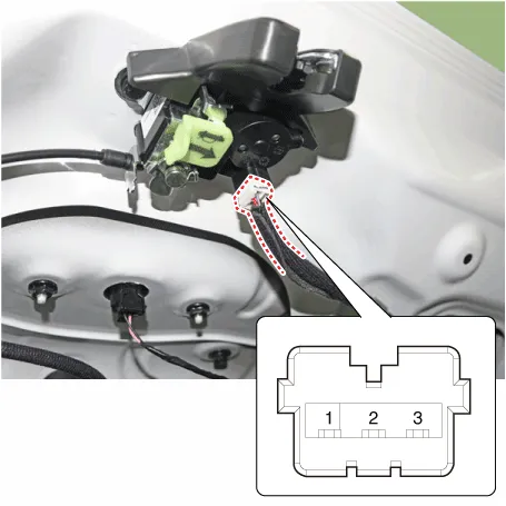
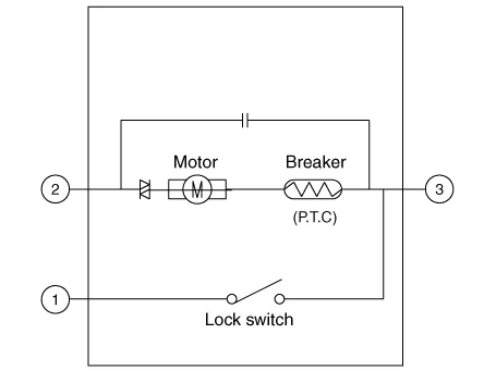
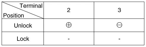
| 3. | Check actuator operation by connecting power and ground according to the table. To prevent damage to the actuator, apply battery voltage only momentarily.
|
| 4. | Checking the trunk of the vehicle power option power refers to the trunk module. |
Power Door Lock Switch
Repair procedures
| Inspection |
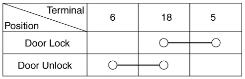
| 1. | Check for continuity between the terminals. If there is an abnormality, replace the switch.
|

| Removal |
|
| 1. | Disconnect the negative (-) battery terminal. |
| 2. | Remove the front door trim. (Refer to Body - "Front Door Trim") |
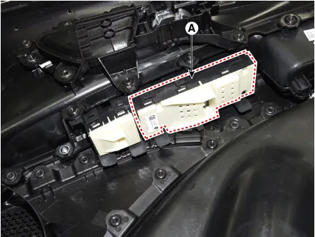
| 3. | Remove the power window switch assembly after disengaging the mounting clips.
|
| Installation |
| 1. | Install the power window switch assembly. |
| 2. | Install the front door trim after connect the connector. |
| 3. | Connect the negative (-) battery terminal. |
Description and operation Description Abbreviation Expalnation ACUAirbag Control UnitADMAssist Door ModuleB_CANBody Controller Area NetworkBCMBody Control ModuleBCWBlind-Spot Collision WarningC_CANChassis Controller Area NetworkCLUCluster ModuleDATCDual Automatic Temp ControlDDMDriver Door ModuleESCElectronic Stability ProgramEMSEngine Management SystemLKASLane Keeping Assist SystemM_CANMulti media Controller Area NetworkMDPSMotor Driven Power SteeringP_CANPowertrain Controller Area NetworkPSMPower Seat ModuleSASSteering Angle SensorSJBSmart Junction BlockSMKSmart Key UnitPDWParking Distance WarningTCUTransmission Control UnitTPMSTire Pressure Monitoring SystemVDCVehicle Dynamic ControlTMUTelematics SystemABSAnti-lock Brake SystemCluster Variant CodingAs we have more options (ESC, MDPS, SCC, etc.
Other information:
Hyundai Elantra (CN7) 2021-2026 Service Manual: High Mounted Stop Lamp
Repair procedures Removal1.Disconnect the negative (-) battery terminal.2.Remove the rear package tray trim.(Refer to Body - "Rear Package Tray Trim")3.Loosen the mounting screws and remove the high mounted stop lamp (A).Installation1.Install the high mounted stop lamp.
Hyundai Elantra (CN7) 2021-2026 Service Manual: Repair procedures
Refrigerant System Service Basics (R-134a)Refrigerant Recovery Use only service equipment that is U.L-listed and is certified to meet the requirements of SAE J2210 to remove HFC-134a(R-134a) from the air conditioning system. • Air conditioning refrigerant or lubricant vapor can irritate your eyes, nose, or
Categories
- Manuals Home
- Hyundai Elantra Owners Manual
- Hyundai Elantra Service Manual
- General Tightening Torque Table. General information
- Rear Seats
- Engine Mechanical System
- New on site
- Most important about car
