Hyundai Elantra (CN7): Rear Glass Defogger / Rear Glass Defogger Switch
Hyundai Elantra (CN7) 2021-2025 Service Manual / Body Electrical System / Rear Glass Defogger / Rear Glass Defogger Switch
Repair procedures
| Diagnosis with Diagnostic tool |
Diagnosis with Diagnostic tool
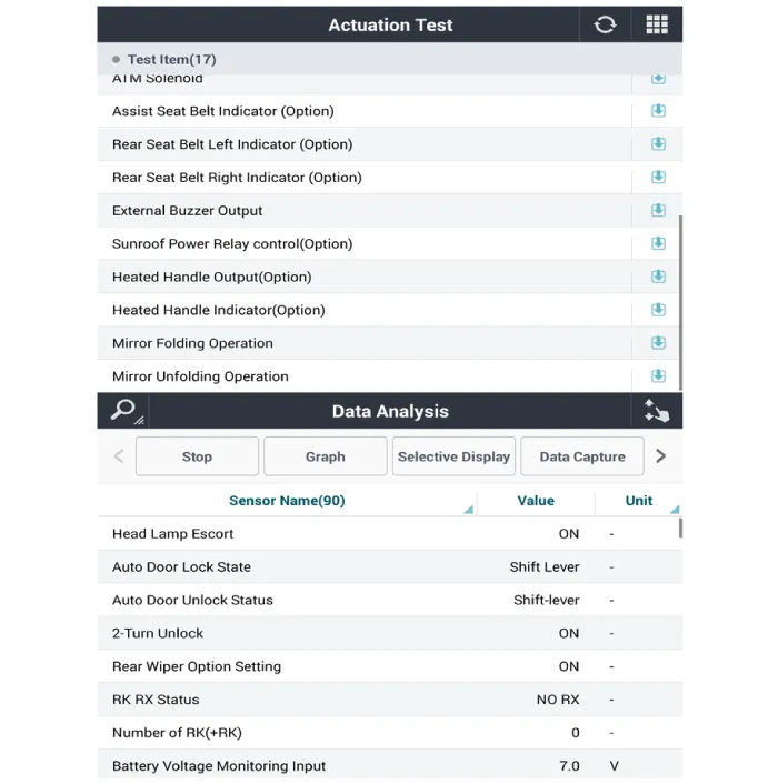
| 1. | In the body electrical system, failure can be quickly diagnosed by using the vehicle diagnostic system (Diagnostic tool). The diagnostic system (Diagnostic tool) provides the following information.
|
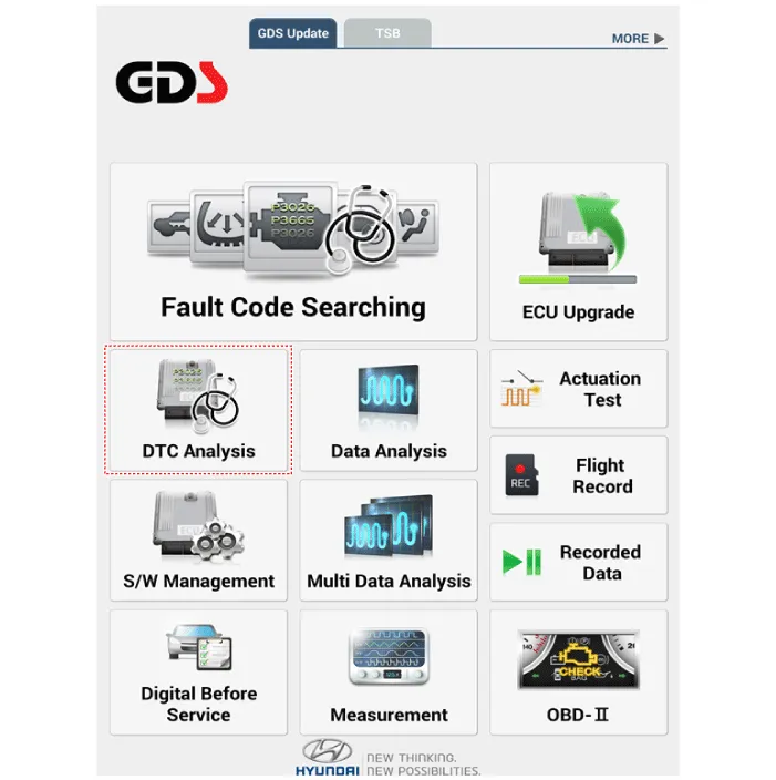
| 2. | If diagnose the vehicle by Diagnostic tool, select "DTC Analysis" and "Vehicle".
|
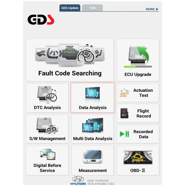
| 3. | Select the 'Data Analysis' and 'Car model'.
|
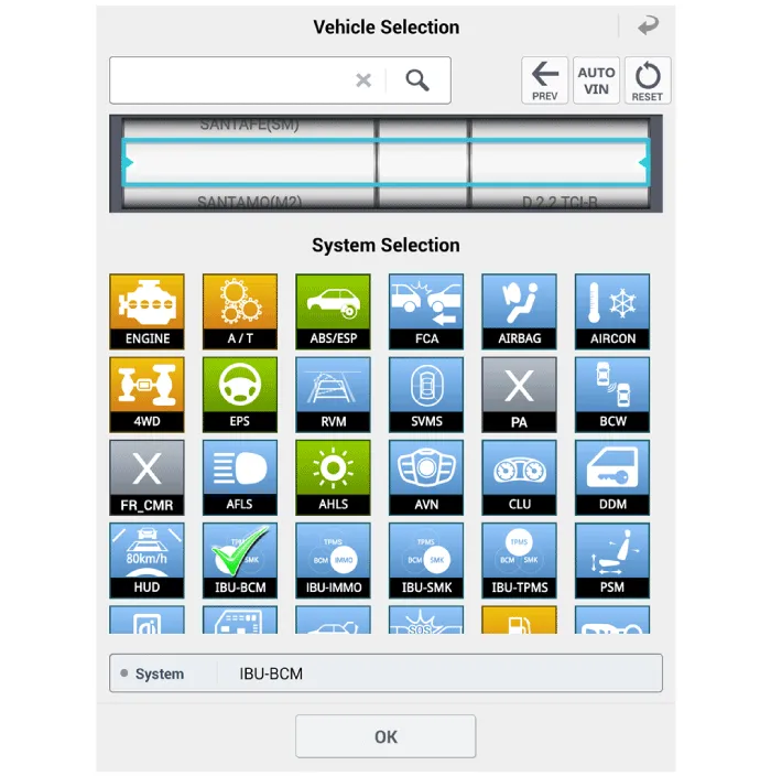
| 4. | Select the 'IBU_BCM' to search the current state of the input/output data.
|
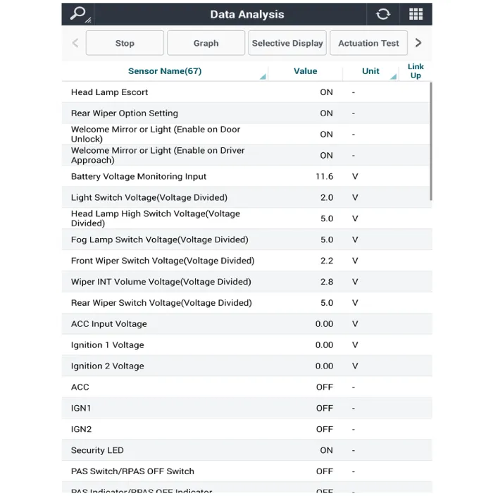
| 5. | To forcibly actuate the input value of the module to be checked, select option 'Actuation Test'.
|
| Removal |
| 1. | Disconnect the negative (-) battery terminal. |
| 2. | Remove the heater and A/C controll unit. (Refer to Heating, Ventilation, Air conditioning - "Heater & A/C Control Unit (Dual)") |
| Installation |
| 1. | Install the heater and A/C control unit. |
| 2. | Connect the negative (-) battery terminal. |
Repair procedures Inspection • Wrap tin foil around the end of the voltmeter test lead to prevent damaging the heater line.
Other information:
Hyundai Elantra (CN7) 2021-2025 Service Manual: Parking Distance Warning (PDW) Sensor
Schematic diagrams Circuit Diagram Repair procedures Removal1.Remove the bumper cover.(Refer to Body - "Front Bumper Cover")(Refer to Body - "Rear Bumper Cover")2.Disconnect the ultrasonic sensor connector (A) and remove the ultrasonic sensor (B).
Hyundai Elantra (CN7) 2021-2025 Service Manual: Parking Collision-Avoidance Assist (PCA)
Components and components location Components and Components Location Schematic diagrams Schematic DiagramsParking Collision-Avoidance Assist (PCA) Ultrasonic sensorParking Collision-Avoidance Assist (PCA) Rear view camera Repair procedures RemovalParking Collision-Avoidance Assist (PCA) Unit1.
Categories
- Manuals Home
- Hyundai Elantra Owners Manual
- Hyundai Elantra Service Manual
- Emergency situations
- Tire Specification and Pressure Label, Engine Number
- Tires and Wheels
- New on site
- Most important about car
Copyright © 2025 www.helantra7.com - 0.0168