Hyundai Elantra (CN7): Integrated Body Control Unit (IBU) / Repair procedures
Hyundai Elantra (CN7) 2021-2026 Service Manual / Body Electrical System / Integrated Body Control Unit (IBU) / Repair procedures
| Removal |
| 1. | Disconnect the negative (-) battery terminal. |
| 2. | Remove the glove box housing cover. (Refer to Body - "Glove Box Housing Cover") |
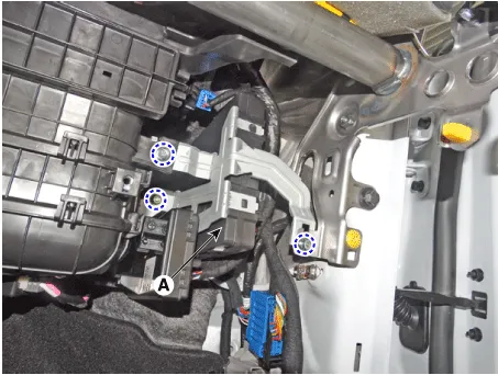
| 3. | Remove the IBU unit (A) after loosening mounting nuts.
|
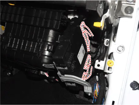
| 4. | Remove the IBU after disconnecting IBU connectors.
|
| Installation |
| 1. | Connect the integrated body control module connector. |
| 2. | Install the integrated body control module. |
| 3. | Install the glove box housing cover. |
| 4. | Connect the negative (-) battery terminal. |
| Diagnosis With Diagnostic tool |
| 1. | In the body electrical system, failure can be quickly diagnosed by using the vehicle diagnostic system (Diagnostic tool).
|
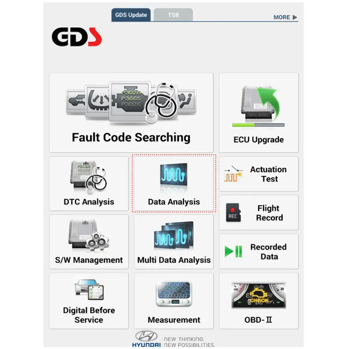
| 2. | If diagnose the vehicle by Diagnostic tool, select "DTC Analysis" and "Vehicle".
|

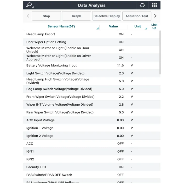
| 3. | If check current status, select the "Data Analysis" and "Car model".
|
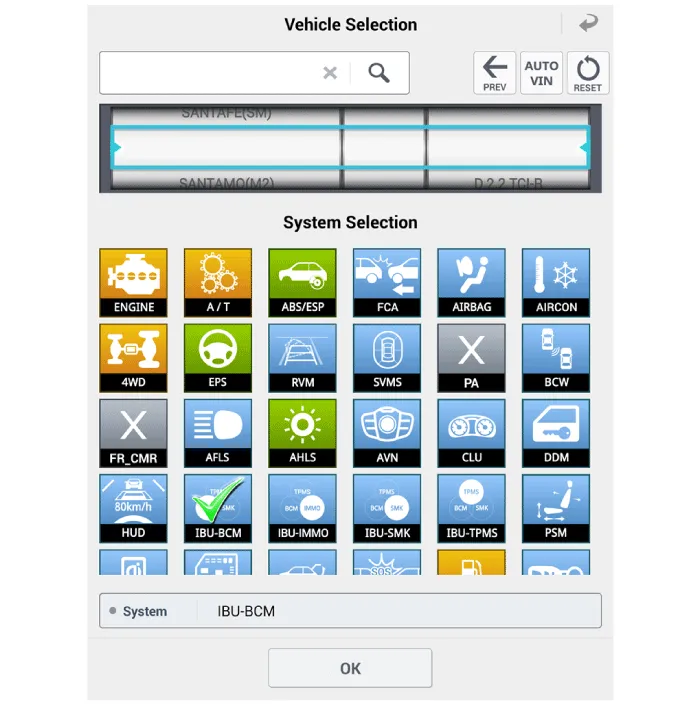
| 4. | Select the 'IBU_BCM' to search the current state of the input/output data.
|
Circuit DiagramWith Smart KeyWithout Smart Key
Other information:
Hyundai Elantra (CN7) 2021-2026 Service Manual: Compressor
Description and operation DescriptionThe compressor is the power unit of the A/C system.It is located on the side of engine block and driven by a V-belt of the engine.The compressor changes low pressure and low temperature refrigerant gas into high pressure and high temperature refrigerant gas.
Hyundai Elantra (CN7) 2021-2026 Service Manual: Components and components location
C
Categories
- Manuals Home
- Hyundai Elantra Owners Manual
- Hyundai Elantra Service Manual
- General Tightening Torque Table. General information
- Body Electrical System
- Auto Hold. Warning messages
- New on site
- Most important about car

Copyright © 2026 www.helantra7.com - 0.0143