Hyundai Elantra (CN7): Motor Driven Power Steering / Schematic diagrams
| Schematic Diagrams |
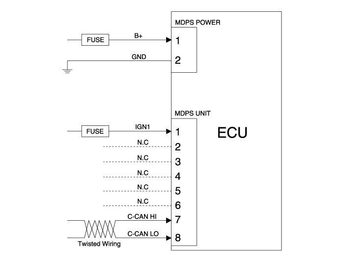
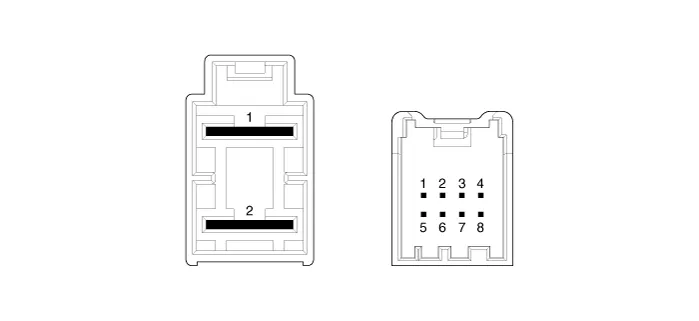
| Terminal function |
|
Type
|
Pin No
|
Description
|
| Battery | 1 | Battery + |
| 2 | Battery - | |
| VSS | 1 | IGN |
| 2 | - | |
| 3 | - | |
| 4 | - | |
| 5 | - | |
| 6 | - | |
| 7 | HIGH CAN | |
| 8 | LOW CAN |
Components 1. Steering wheel2. Steering column3. MDPS power pack4. Universal joint5. Dust cap6. Tie rod end7. Bellows8. Steering gear box
A/S Repair produresMDPS System A/S Workflow ※ For detailed DTC or other DTC A/S procedures, see "CN7 MDPS DTC Diagnostic Guide" ①Noise / malfunction Inspection② Warning lamp (DTC) / CAN Line error2 - 1 Checking Connectors and Wiring1.
Other information:
Hyundai Elantra (CN7) 2021-2026 Service Manual: Rear Combination Lamp
Repair procedures RemovalOutside Combination Lamp1.Disconnect the negative (-) battery terminal.2.Remove the combination lamp cover (A).3.Disconnect the rear combination lamp connector (A).4.Loosen the mounting nuts and remove the rear conbination lamp (A).
Hyundai Elantra (CN7) 2021-2026 Service Manual: Troubleshooting
TroubleshootingWireless Power Charger System Troubleshooting Trouble status Inspection item Inspection Not chargedCheck the mobile phone status R-1Amber LED blinks OvercurrentR-2OverheatingR-2Foreign matterR-2R-1.
Categories
- Manuals Home
- Hyundai Elantra Owners Manual
- Hyundai Elantra Service Manual
- Drive Mode
- Suspension System
- Vehicle Information
- New on site
- Most important about car
