Hyundai Elantra (CN7): Starting System / Starter Relay
Hyundai Elantra (CN7) 2021-2026 Service Manual / Engine Electrical System / Starting System / Starter Relay
Repair procedures
| Inspection |
| 1. | Turn ignition switch OFF and disconnect the negative (-) battery cable. |
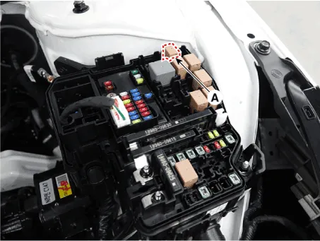
| 2. | Remove the fuse box cover. |
| 3. | Remove the starter relay (A).
|
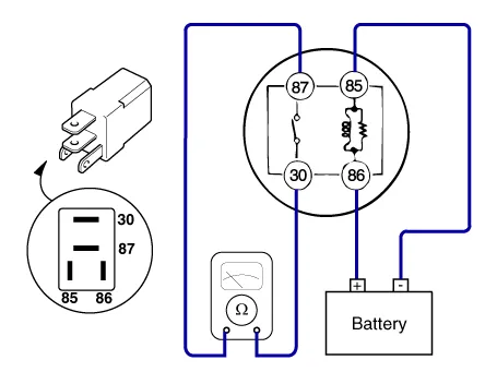
| 4. | Using an ohmmeter, check that there is continuity between each terminal.
|
| 5. | Apply 12V to terminal 85 and ground to terminal 86. Check for continuity between terminals 30 and 87.
|
| 6. | If there is no continuity, replace the starter relay. |
| 7. | Install the starter relay. |
| 8. | Install the fuse box cover. |
Description and operation DescriptionThe starting system includes the battery, starter, solenoid switch, ignition switch, inhibitor switch, ignition lock switch, connection wires and the battery cable.
Other information:
Hyundai Elantra (CN7) 2021-2026 Service Manual: Description and operating principle
Description and OperationWireless Power Charger SystemDuring ACC or IG ON, battery voltage is supplied to the wireless power charger system to transmit an output of 5 W to mobile phone. Mobile phones certified with the wireless charging standard WPC (Qi 1.
Hyundai Elantra (CN7) 2021-2026 Service Manual: Power Mosfet
Description and operation DescriptionIt is installed to the DATC and adjusts the fan rpm by precisely controlling the voltage applied to the blower motor. Repair procedures Inspection1.Manually operate the control switch and measure the voltage of the blower motor.
Categories
- Manuals Home
- Hyundai Elantra Owners Manual
- Hyundai Elantra Service Manual
- Driver assistance system
- Drive Mode
- Suspension System
- New on site
- Most important about car

Copyright © 2026 www.helantra7.com - 0.0198