Hyundai Elantra (CN7): AVN System / USB Jack
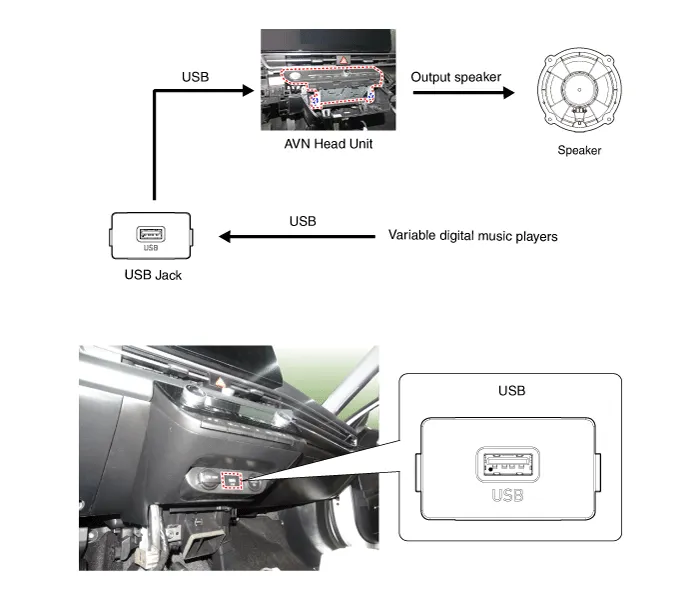
Description and operation
| Description |
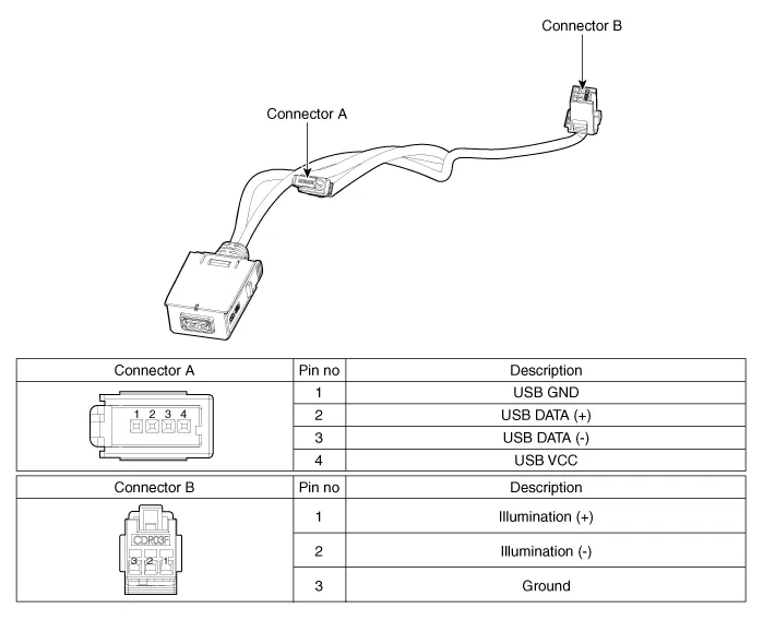
Schematic diagrams
| Circuit Diagram |
Repair procedures
| Removal |
| 1. | Disconnect the battery (-) terminals. |
| 2. | Remove the floor console assembly. (Refer to Body - "Floor Console Assembly") |
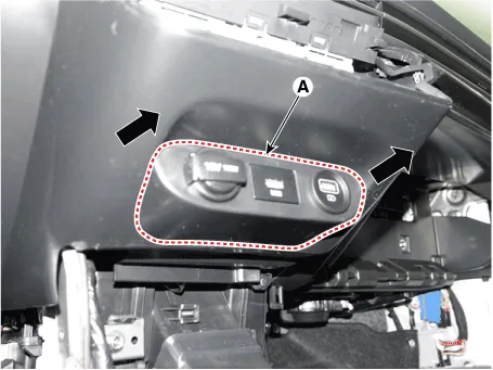
| 3. | Remove the UBS port assembly (A).
|
| 4. | Remove the avn head unit. (Refer to AVN System - "AVN(Audio Video Navigation) head unit") |
| 5. | Disconect the USB connector (A).
|

| 6. | Disconect the USB connector (B). [Display Audio only]
|
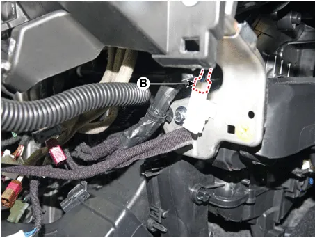
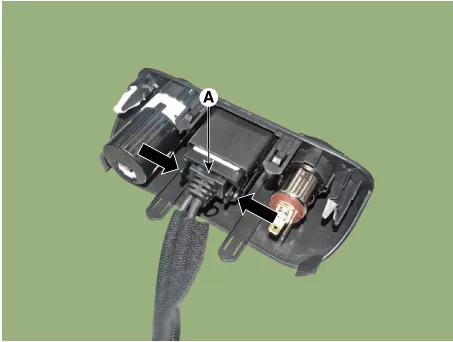
| 7. | Remove the USB jack (A) after releasing the fixed hooks.
|
| Installation |
| 1. | Connect the USB jack connector. |
| 2. | Install the USB jack. |
| 3. | Install the UBS port assembly. |
Repair procedures Inspection1.Troubleshooting for Speaker(1)Basic inspection of speakerInspect the sound from speaker after verifying that the speaker mounting screws is removed and the wiring connector is connected precisely to remove vibration transmitted from body trims and surrounding parts.
Repair procedures Inspection1.Disconnector the negative (-) battery terminal.2.Remove the overhead console lamp.(Refer to Body Electrical System - "Overhead Console Lamp")3.
Other information:
Hyundai Elantra (CN7) 2021-2026 Service Manual: Description and operation
D
Hyundai Elantra (CN7) 2021-2026 Service Manual: Troubleshooting
Trouble Symptom ChartsTrouble Symptom 1Trouble Symptom 2 Trouble symptom Probable cause Remedy The set vehicle speed varies greatly upward or downward"Surging" (repeated alternating acceleration and deceleration) occurs after settingMalfunction of the vehicle speed se
Categories
- Manuals Home
- Hyundai Elantra Owners Manual
- Hyundai Elantra Service Manual
- Front Radar Unit
- Integrated Thermal Management Module (ITM)
- Front Bumper
- New on site
- Most important about car
