Hyundai Elantra (CN7): Cooling System / Components and components location
| Components |
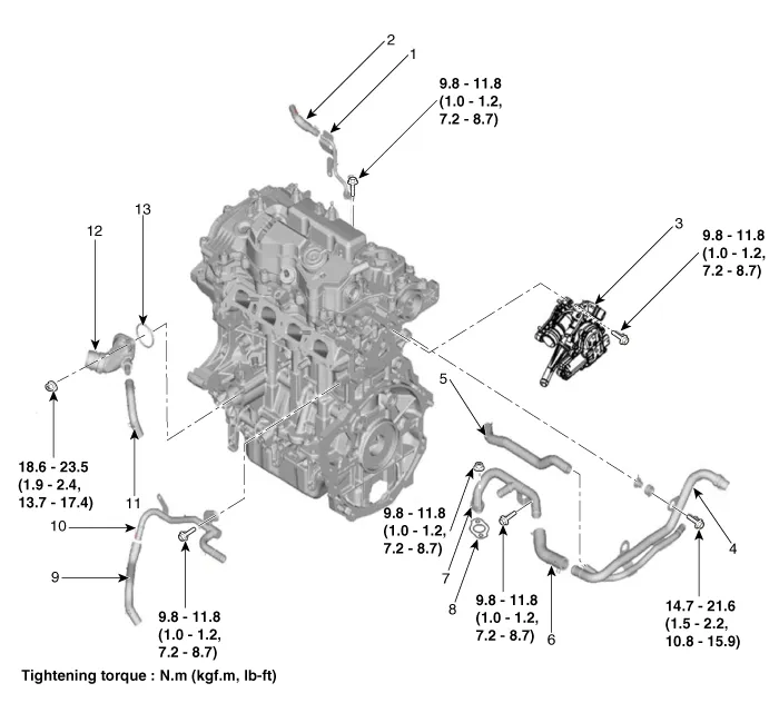
| 1. Water pipe 2. Water hose 3. Integrated thermal management module (ITM) 4. Heater pipe 5. Turbo charger coolant hose 6. Heater hose 7. Heater pipe A | 8. Heater pipe A gasket 9. Oil cooler hose A 10. Oil cooler pipe 11. Oil cooler hose B 12. Water inlet fitting 13. Water inlet fitting O-ring |
Engine Overheat Troubleshooting Inspection Remedy Visual inspectionInspect for shortage of coolant in reservoir tank .
Other information:
Hyundai Elantra (CN7) 2021-2026 Service Manual: Front Radar Unit
Components and components location Components Location1. Front rader unit Specifications Specification Item Specification Power supply (V)12Operation voltage (V)9 - 16 Schematic diagrams Circuit DiagramTerminal function Pin No Te
Hyundai Elantra (CN7) 2021-2026 Service Manual: Parking Distance Warning (PDW)
Description and operation Description• PDW consists of 8 sensors (front : 4 units, rear : 4 units) that are used to detect obstacles and transmit the result in three separate warning levels, the first, second and third to IBU via LIN communication.
Categories
- Manuals Home
- Hyundai Elantra Owners Manual
- Hyundai Elantra Service Manual
- Specifications
- Vehicle Information
- Body Electrical System
- New on site
- Most important about car
