Hyundai Elantra (CN7): Lubrication System / Components and components location
Hyundai Elantra (CN7) 2021-2026 Service Manual / Engine Mechanical System / Lubrication System / Components and components location
| Components |
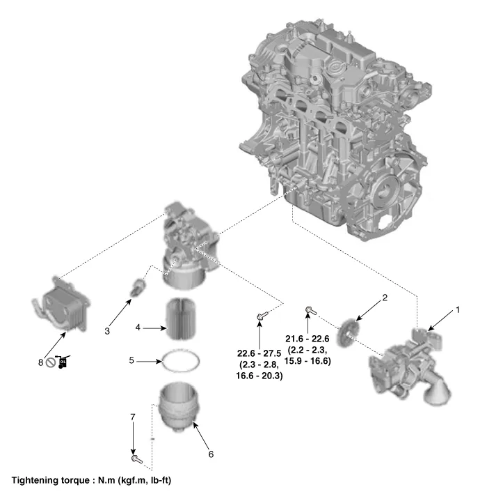
| 1. Variable oil pump 2. Variable oil pump sproket 3. Oil Pressure & temperature sensor 4. Oil filter | 5. Filter cap O-ring 6. Filter cap 7. Safety pin 8. Oil cooler |
Engine oil flow diagram
Other information:
Hyundai Elantra (CN7) 2021-2026 Service Manual: Climate Control Air Filter
Description and operation Description The climate control air filter is located in the blower unit. It eliminates foreign materials and odor. The particle filter performs a role as an odor filter as well as a conventional dust filter to ensure comfortable interior environment.
Hyundai Elantra (CN7) 2021-2026 Service Manual: Repair procedures
Inspection1.Check for resistance between terminals in each switch position (LH).[LH : Audio + Hands free] Switch Resistance (±5%) SEEK Up430 ΩSEEK Down1.11 kΩMODE2.11 kΩMUTE3.11 kΩVolume (+)4.
Categories
- Manuals Home
- Hyundai Elantra Owners Manual
- Hyundai Elantra Service Manual
- Troubleshooting
- Rear Seats
- Instrument Panel Overview
- New on site
- Most important about car

Copyright © 2026 www.helantra7.com - 0.0192