
Hyundai Elantra (CN7): Rear Suspension System / Components and components location
Hyundai Elantra (CN7) 2021-2026 Service Manual / Suspension System / Rear Suspension System / Components and components location
| Components |
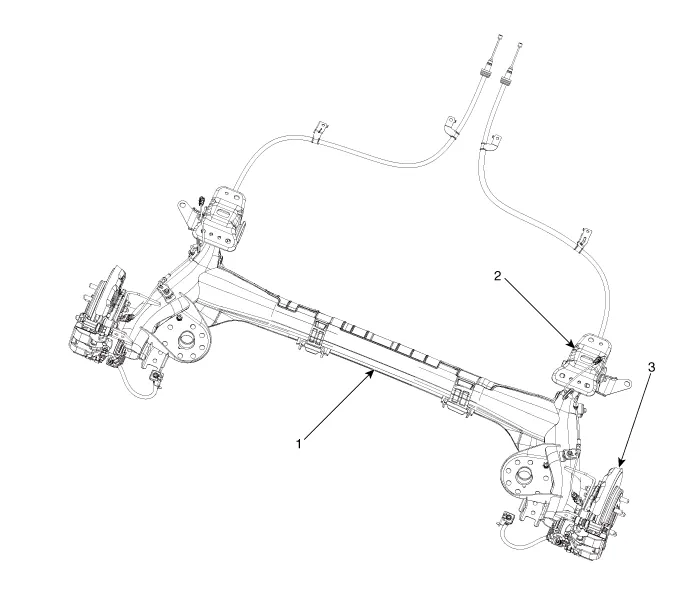
| 1. Rear torsion beam axle 2. Rear torsion beam chassis bracket | 3. Rear axle |
Components and components location Components 1. Insulator cap2. Insulator3. Bumper rubber4. Spacer5. Dust cover6. Rear shock absorber Repair procedures Removal1.
Categories
- Manuals Home
- Hyundai Elantra Owners Manual
- Hyundai Elantra Service Manual
- Instrument Cluster
- Troubleshooting
- Engine Control / Fuel System
- New on site
- Most important about car

Copyright В© 2026 www.helantra7.com - 0.0189