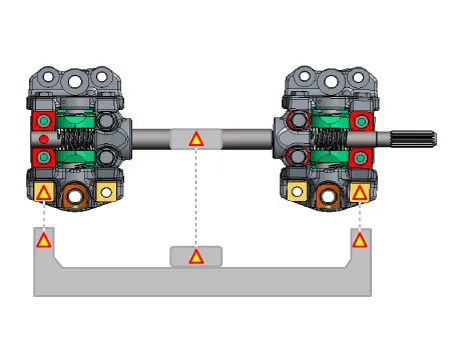
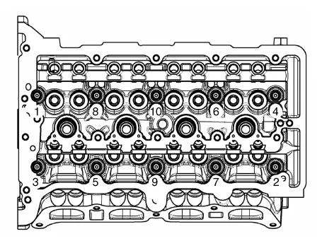
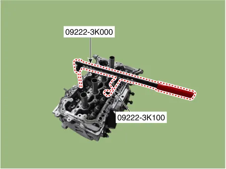
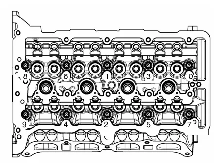
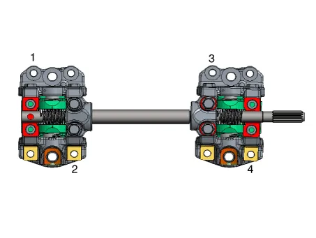
If CVVD fixing jig is available, be sure to work by using it. When Using the CVVD fixture 1. When installing the CVVD assembly mounting bolts (M6), tighten sequence shown. Tightening torque : 1ST 4.9 - 6.9 N.m (0.5 - 0.7 kgf.m, 3.6 - 5.1 lb-ft) 2nd 9.8 - 11.8 N.m (1.0 - 1.2 kgf.m, 7.2 - 8.7 lb-ft) |
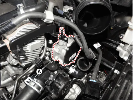
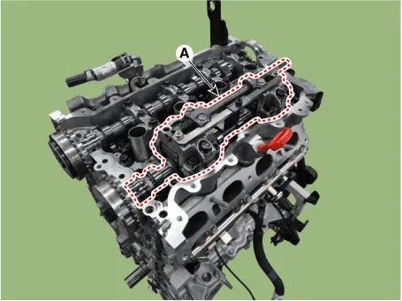
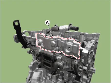
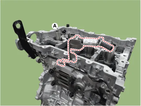
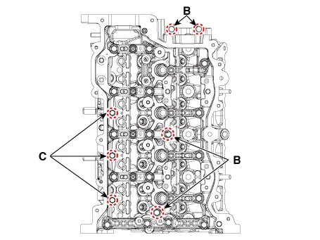
2. Remove the CVVD fixture (A). 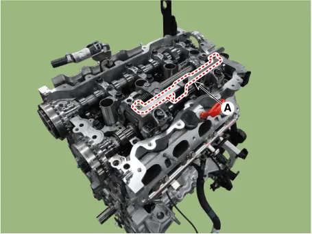
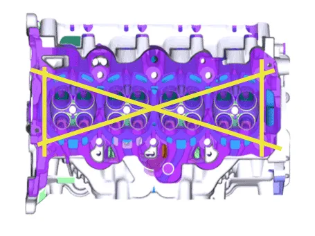
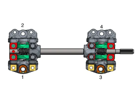
3. Provisionally tighten the CVVD assembly mounting bolts (M8) in sequence shown below. Tightening torque : 9.8 - 11.8 N.m (1.0 - 1.2 kgf.m, 7.2 - 8.7 lb-ft) |
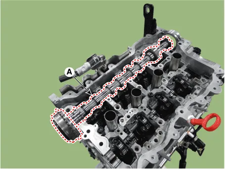
4. Remove the CVVD assembly mounting bolts (M6) (A). 
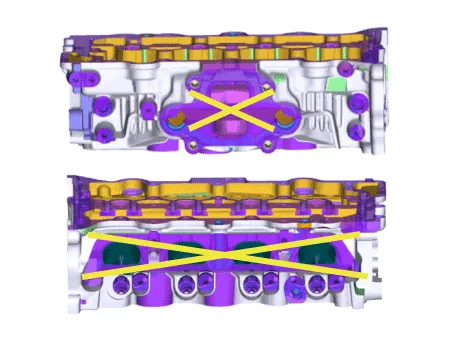
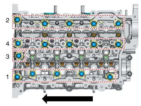
5. Provisionally tighten the CVVD assembly mounting bolts (M6) in sequence shown below. Tightening torque : 4.9 - 6.9 N.m (0.5 - 0.7 kgf.m, 3.6 - 5.1 lb-ft) |

6. Tighten the CVVD assembly mounting bolts (M8) in sequence shown below. Tightening torque : 18.6 - 22.6 N.m (1.9 - 2.3 kgf.m, 13.7 - 16.6 lb-ft) |

7. Tighten the CVVD assembly mounting bolts (M6) in sequence shown below. Tightening torque : 9.8 - 11.8 N.m (1.0 - 1.2 kgf.m, 7.2 - 8.7 lb-ft) |

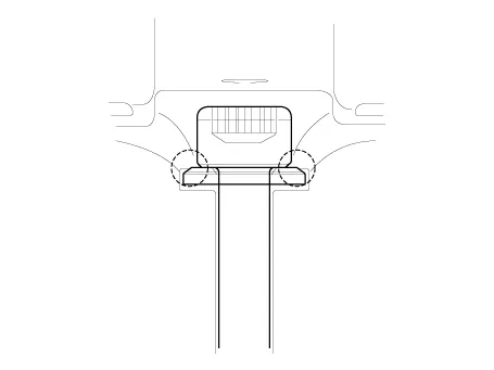
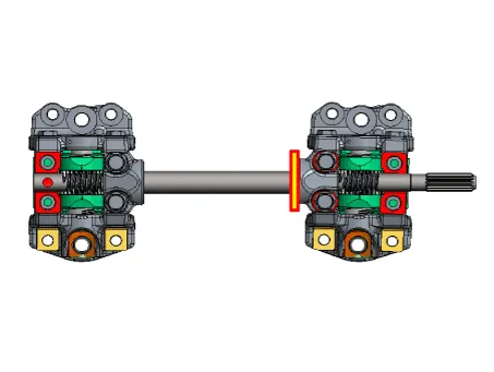
8. Measure the clearance between the control shaft bearing cap and the end of control shaft using a clearance gauge. Clearance : 0.0 - 0.05 mm (0.0 - 0.002 in.) |
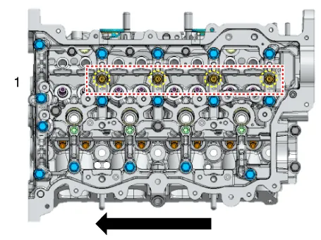
When not using the CVVD fixture 1. Provisionally tighten the CVVD assembly mounting bolts (M6) in sequence shown below. Tightening torque : 4.9 - 6.9 N.m (0.5 - 0.7 kgf.m, 3.6 - 5.1 lb-ft) |

2. Provisionally tighten the CVVD assembly mounting bolts (M8) in sequence shown below. Tightening torque : 9.8 - 11.8 N.m (1.0 - 1.2 kgf.m, 7.2 - 8.7 lb-ft) |
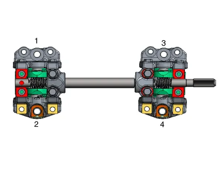
3. Tighten the CVVD assembly mounting bolts (M8) in sequence shown below. Tightening torque : 18.6 - 22.6 N.m (1.9 - 2.3 kgf.m, 13.7 - 16.6 lb-ft) |

4. Tighten the CVVD assembly mounting bolts (M6) in sequence shown below. Tightening torque : 9.8 - 11.8 N.m (1.0 - 1.2 kgf.m, 7.2 - 8.7 lb-ft) |

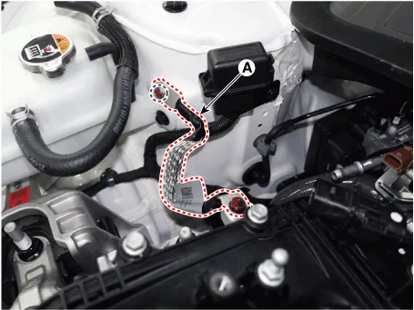
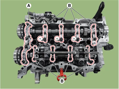
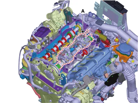
5. Release the torque of control shaft bearing cap bolt (A). 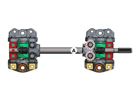
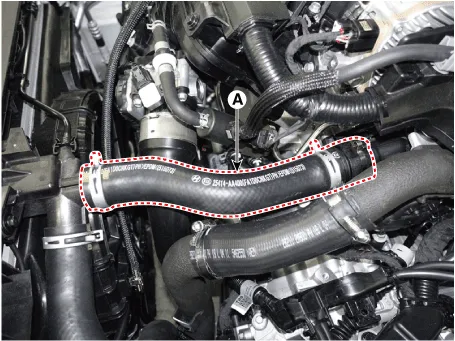
6. Push the control shaft bearing cap as close as possible in the direction of the arrow. 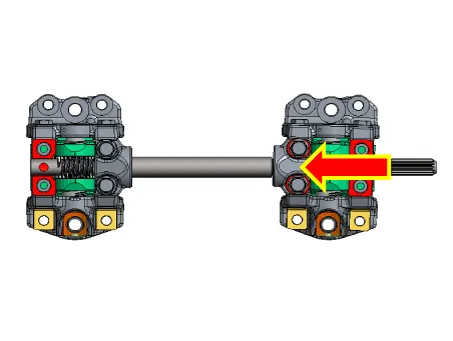
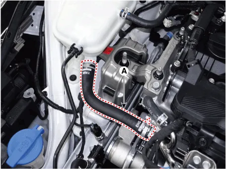
7. Install the control shaft bearing cap mounting bolts (A). Tightening torque : 9.8 - 11.8 N.m (1.0 - 1.2 kgf.m, 7.2 - 8.7 lb-ft) |
8. Measure the clearance between the control shaft bearing cap and the end of control shaft using a clearance gauge. Clearance : 0.0 - 0.05 mm (0.0 - 0.002 in.) |
|