Hyundai Elantra (CN7): Cylinder Head Assembly / CVVD Assembly
Description and operation
| Description |

| Operation Principle |
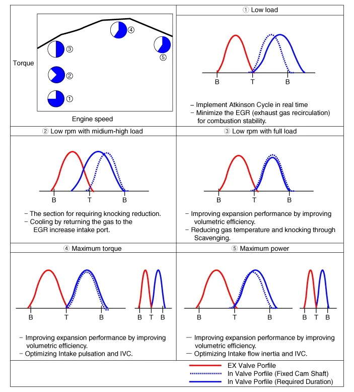
| Optimum Valve Timing by Engine Load |
Repair procedures
| Removal |
| 1. | Disconnect the battery negative terminal. |
| 2. | Remove the cylinder head cover. (Refer to Cylinder Head Assembly - "Cylinder Head Cover") |
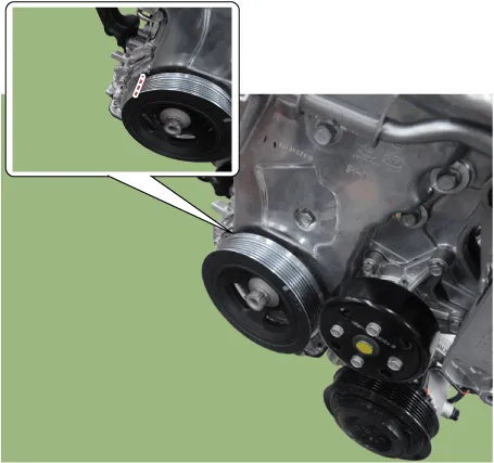
| 3. | Turn the crankshaft damper pulley so that No. 1 piston is at top dead center.
|

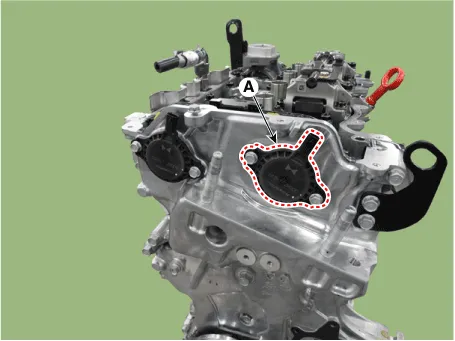
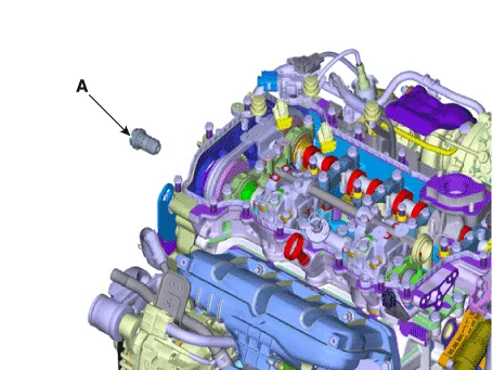
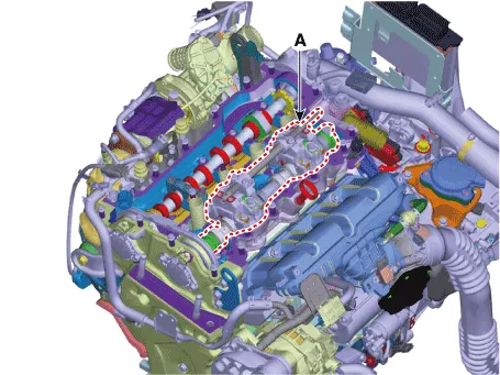
| 4. | Remove the Intake variable force solenoid (VFS) valve (A).
|
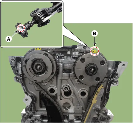
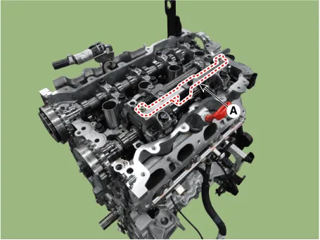
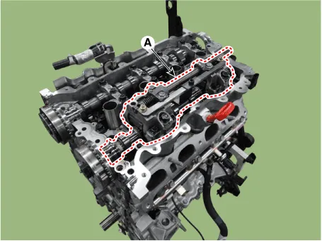
| 5. | Remove the cam to cam guide (A).
|

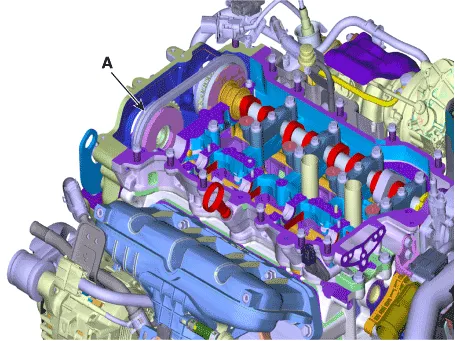
| 6. | Reomve the front bearing cap (A) and intake camshaft bearing caps (B).
|

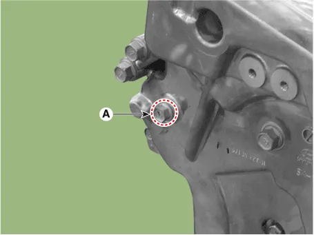
| 7. | Remove the service hole bolt (A).
|
| 8. | Remove the engine mounting support bracket. (Refer to Engine and Transaxle Assembly - "Engine Mounting") |
| 9. | Lift the engine using the jack to obtain space. |
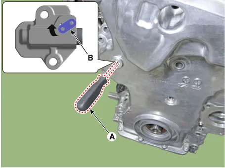
| 10. | Release the lock by putting down rachet plate (B) of timing chain tensioner with using back of tiny awl (A).
|

| 11. | Remove the intake oil control valve (OCV) & center bolt (A).
|

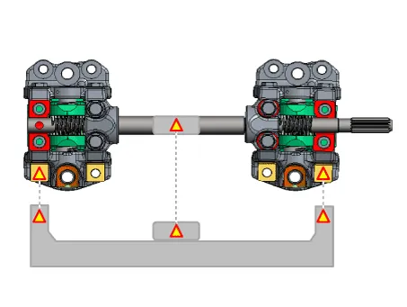
| 12. | Remove the CVVD assembly.
When Using the CVVD fixture
When not using the CVVD fixture
|
| 13. | Remove the Intake CVVT (A).
|
| Installation |
| 1. | Install the Intake CVVT (A).
|
| 2. | Install the CVVD assembly (A).
|


| 3. | Install the intake OCV & center bolt (A).
|
| 4. | Compress the timing chain tensioner piston.
|


| 5. | Install the front bearing cap and camshaft bearing cap
|
| 6. | Remove the fine gimlets (A) that hold the timing chain tensioner.
|
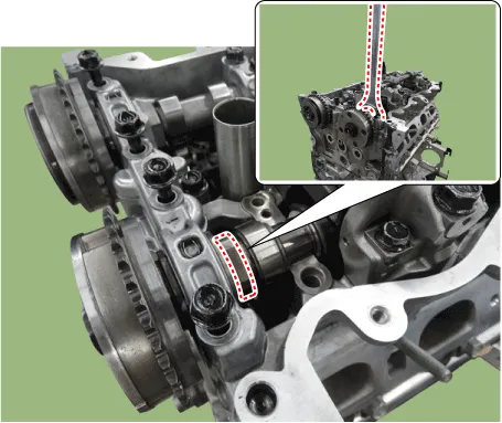
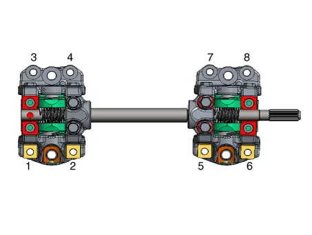
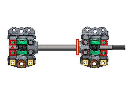
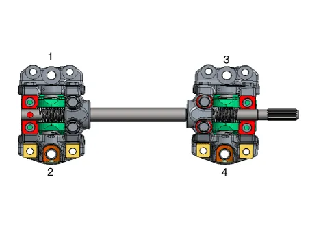
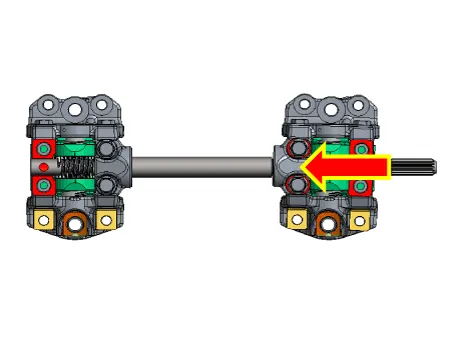
| 7. | When installing the timing chain, be sure that the timing mark (A) of each sprocket is matched with the timing mark (B) (color link) of the timing chain. [Intake CVVT Timing Mark]
[Exhaust CVVT Timing Mark]
|
| 8. | Install the cam to cam guide (A).
|
| 9. | Install the intake variable force solenoid (VFS) valve (A).
|
| 10. | Install the cylinder head cover. (Refer to Cylinder Head Assembly - "Cylinder Head Cover") |
Repair procedures Removal 1.Disconnect the battery negative terminal.2.Remove the cylinder head cover. (Refer to Cylinder Head Assembly - "Cylinder Head Cover")3.
Repair procedures Removal • Use Fender cover to avoid damaging painted surfaces.• To avoid damaging the cylinder head, wait until the engine coolant temperature drops below normal temperature before removing it.
Other information:
Hyundai Elantra (CN7) 2021-2026 Service Manual: Description and operation
DescriptionSystem OverviewThe System offers the following features:– Human / machine interface through a 1-stage button, for terminal switching and engine start.– Control of external relays for ACC / IGN1 / IGN2 terminal switching and STARTER, without use of mechanical ignition switch.
Hyundai Elantra (CN7) 2021-2026 Service Manual: Compressor oil
Repair procedures Oil Specification1.The HFC-134a system requires synthetic (PAG) compressor oil whereas the R-12 system requires mineral compressor oil. The two oils must never be mixed.2.Compressor (PAG) oil varies according to compressor model. Be sure to use oil specified for the model of compressor.
Categories
- Manuals Home
- Hyundai Elantra Owners Manual
- Hyundai Elantra Service Manual
- Front Radar Unit
- Body (Interior and Exterior)
- Integrated Thermal Management Module (ITM)
- New on site
- Most important about car
